|
Open tracings 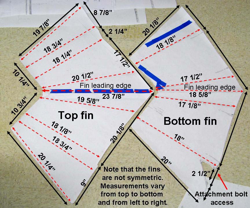 |
Closed tracing 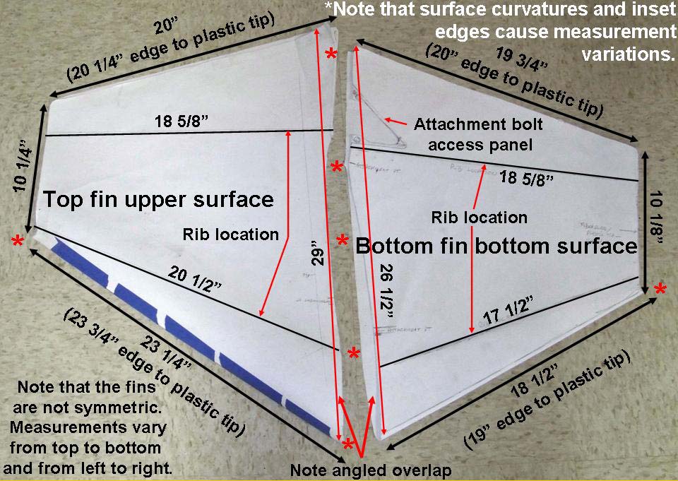 |
Fin production 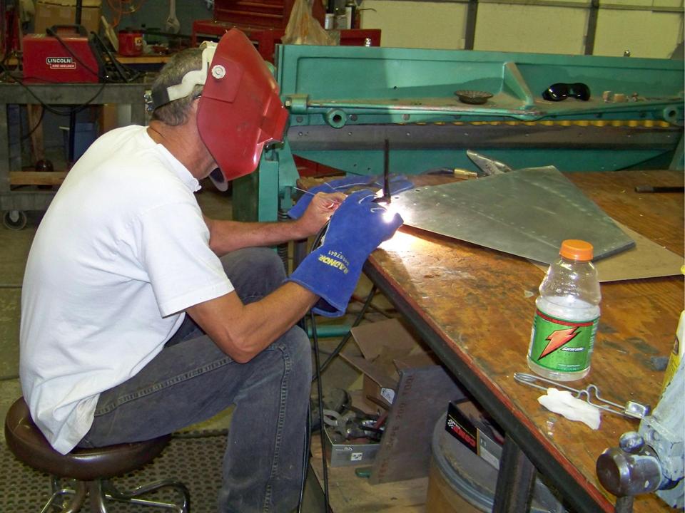 |
I was lucky enough to find two 275-gallon tanks in Don Howell's scrap yard in Tucson, AZ. Those two tanks would serve as the perfect templates for this portion of the project. In addition, I had taken numerous -- and very detailed -- photos of some tanks I found at a warbird museum in Kissimmee, FL, in March of 2005. (Those tanks wound up at the Carolinas Museum in Charlotte, NC.)
Combining the pictures with the many paper tracings I had made, the 275-gallon tank portion of the F-100 project was ready to go. Since we believed the tank fins to be the easiest place to start, I began by enhancing the tank fin tracings. Figure 1, cell 01, shows the unfolded tracings of both top and bottom fins. (Note that the top and bottom fins are slightly different in size and shape.) Cell 02 shows the same tracings folded to show the fins as you would see them on the tank. Cell 03 shows Steve welding a fin that conforms to the tracings.
Note: You can enlarge the pictures by clicking on them. Many of the pictures can be enlarged some more by placing the cursor on them and clicking again. Then maximize the window to get an even closer look.
|
Open tracings |
Closed tracing |
Fin production |
After all four tank fins passed our "quality control" check, I sanded the aluminum with an 800-grit paper to promote better adhesion of a self-etching primer. After spraying the self-etching primer on the surfaces, I sanded the primer lightly, then sprayed a gray primer-filler over that sanded surface. Next, the primer-filler was wet-sanded to produce a really smooth surface that would receive the color coats that would be applied later. Figure 2, cell 01 shows the primer-filler-coated fins. In the meantime, the tank tail cone was made to receive the fins. Cell 02 shows the paper tail cone tracing, the cardboard template, and the completed tail cone. Cell 03 shows the fins attached to the tail cone. (I painted those fins during the breaks in hardware production.)
Note: You can enlarge the pictures by clicking on them. Many of the pictures can be enlarged some more by placing the cursor on them and clicking again. Then maximize the window to get an even closer look.
|
Primed fins 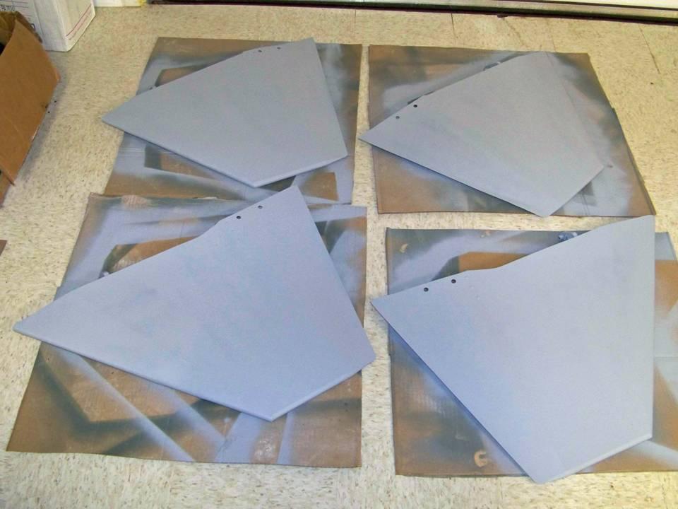 |
Fins and cone  |
Attached fins  |
Comment by Pete Felts:
Those big screws that fasten the tail cone to the tank are called PK screws. (See Figure 2, cell 02, lower left-hand panel.) I don't know what "PK" stands for, but that's what our tin benders in �Nam said they were called. We would use them on the tanks when they got bullet holes in them, take a piece of rubber and one of those screws and you were good to go as long as the pilot remembered to not pressurize the tanks before end of runway check. If the crew at the end of the runway saw a leak, they would send the aircraft back to the ramp and you would miss out on a mission. The wing tanks empty first; then the wing tanks. Everything feeds to the fuselage tank in the center box.
Incidentally, the composite picture in Figure 2, cell 03 shows several views of the tank fins attached to the tank cone, plus a view of some fin attachment back plates. The lower right-hand corner shows a picture of a 1/48-scale model I built and painted in the colors of 56-3189, 309 FBS, 31 FBW, based at George AFB in 1958. This aircraft was flown by Capt. Walt Bruce during the 1958 TAC gun meet. The brightly-painted 275-gallon tanks on 56-3189 became the painting guide for the paint job you will see documented on this web page.
The completion of the tank fins and cone -- a task that consumed four months -- let us switch our attention to the tank itself. To document the work, I transformed the many tracings to a set of work drawings. Figure 3, cell 01, shows a small portion of the collection of tracings. (Note that the left middle panel shows a large sketch of the complete tank.) Cells 02 and 03 show the transformation of the tracings into the work drawings that became the basis for the tank templates.
Note: You can enlarge the pictures by clicking on them. Many of the pictures can be enlarged some more by placing the cursor on them and clicking again. Then maximize the window to get an even closer look.
|
Tank tracings  |
Tank front  |
Tank center  |
Figure 4 continues the documentation of the tank building process. Cells 01 and 02 show the last two drawings of the tank body components. Cell 03 shows a few of the tank accessories. The rounded vent outlet in the center of the composite picture in cell 03 is the product of "lost wax" casting.
Note: You can enlarge the pictures by clicking on them. Many of the pictures can be enlarged some more by placing the cursor on them and clicking again. Then maximize the window to get an even closer look.
|
Back section 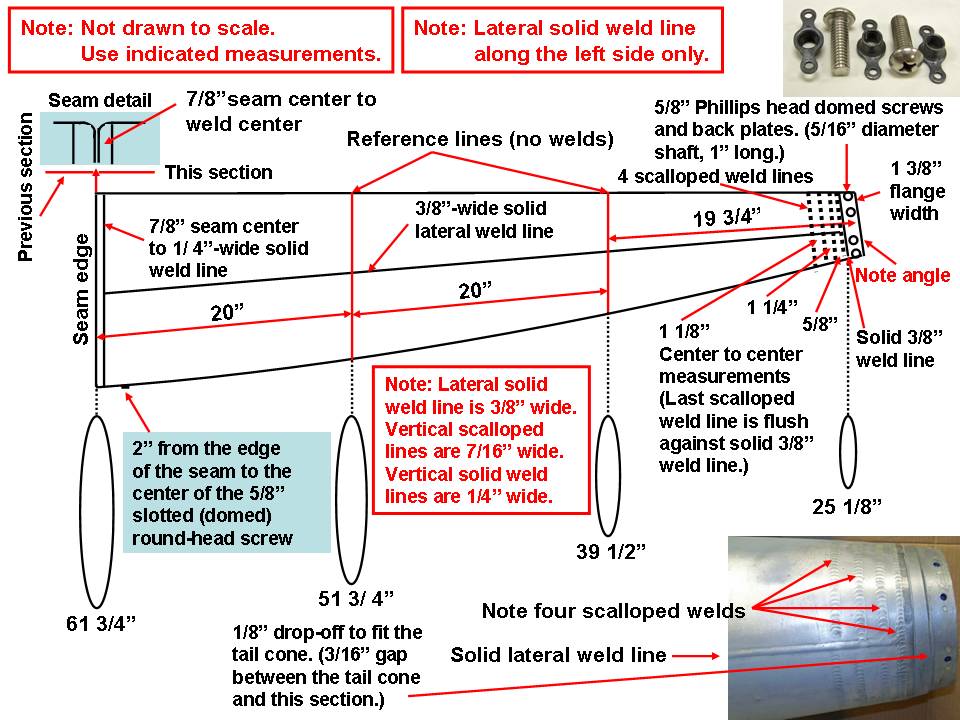 |
Tail cone 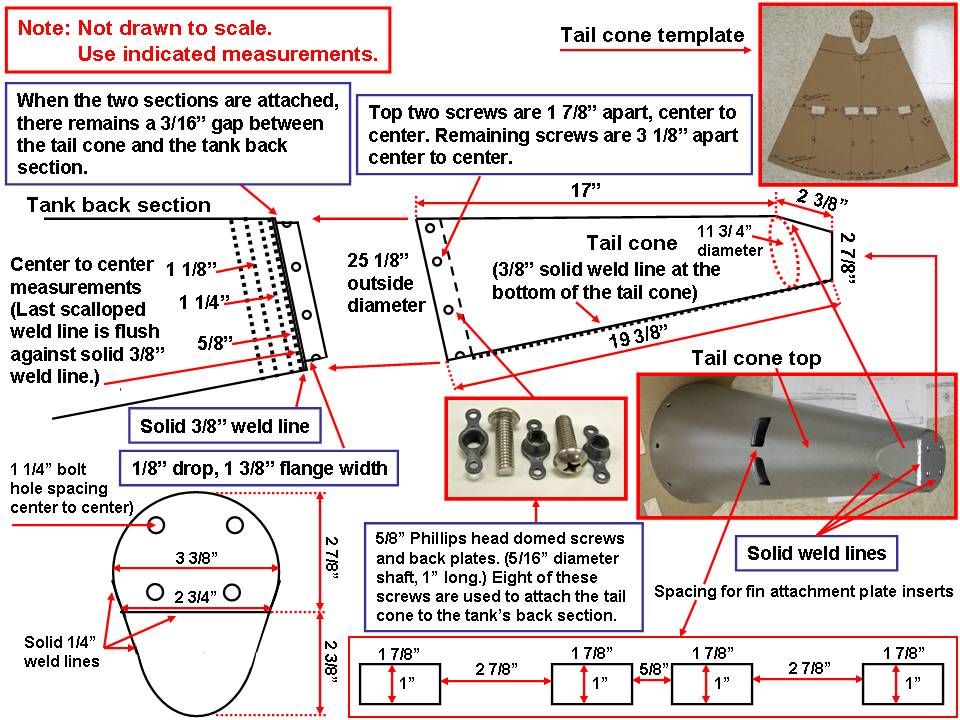 |
Accessories 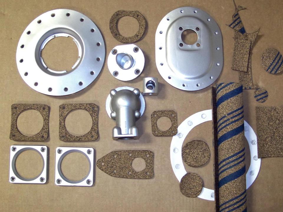 |
Using a set of composite pictures, Figure 5 documents the completion of the building, painting, and displaying steps. Cell 01 shows the original work sketch, the first roll-out of the completed tank, and the start of the complex painting process. (The color bands and the red lightning bolt look a lot better if the color is painted over a solid white background.) Cell 02 documents the completion of the painting process, while cell 03 shows the display in the F-100 Building. (And, yes, that inset picture in cell 03 shows the much simpler paint job on the first 275-gallon tank that was completed a year earlier. That tank, too, is hanging in the F-100 Building.)
Note: You can enlarge the pictures by clicking on them. Many of the pictures can be enlarged some more by placing the cursor on them and clicking again. Then maximize the window to get an even closer look.
|
First paint 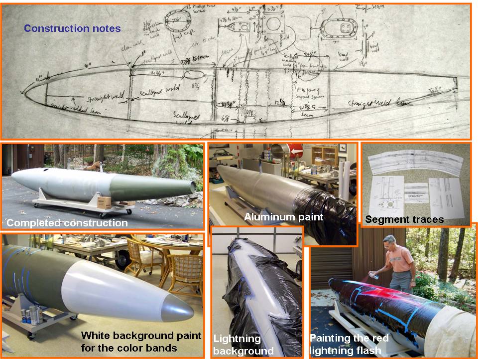 |
Painting completion 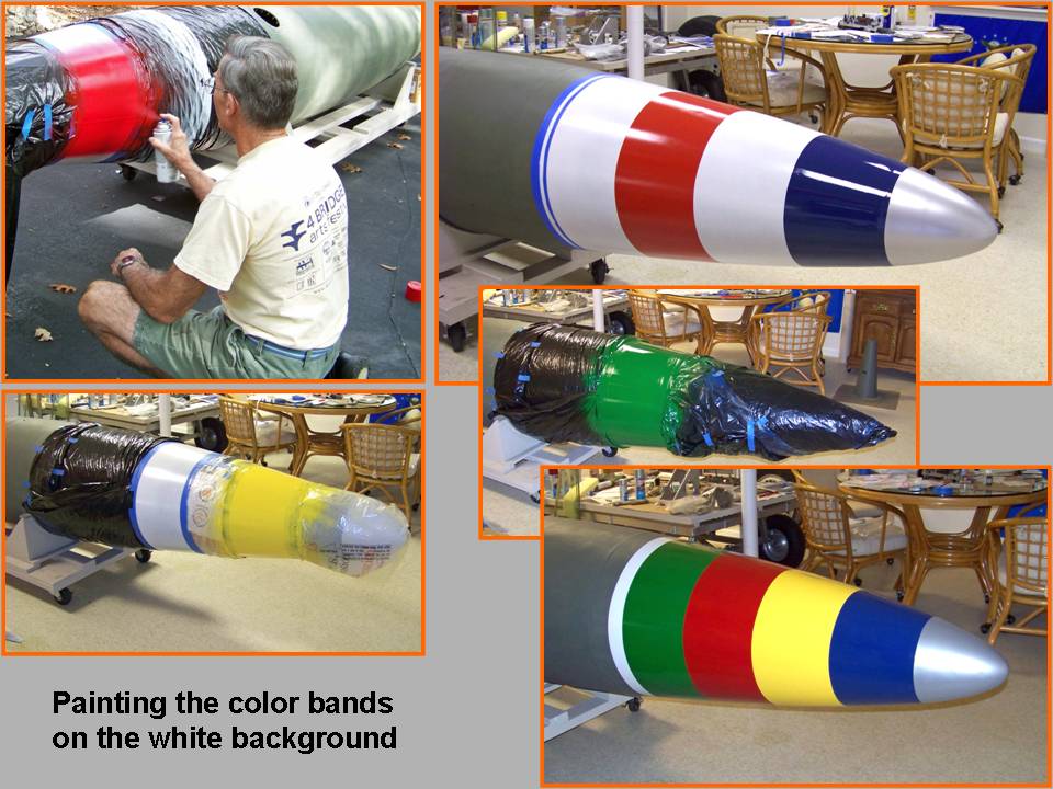 |
Tank display  |
Working on the two 275-gallon tanks consumed an enormous amount of time, but it also provided a really good preparation for the major fuselage work. In retrospect, it would have been a lot simpler -- and cheaper -- to take the detailed drawings and the few salvaged scrap pieces to a good boat yard that builds metal pontoon boats. Never mind the second thoughts ... working on the 275-gallon tanks was never boring and it sure kept me off the street and out of trouble!
While the rebuilding and restoring efforts are important, please remember that the main focus of the F-100 project is its database. If you can supply stories and pictures that reflect your experience with the Hun, please do so. (You can click on the Contact me link to send me an email.) The objective is to develop a very comprehensive personal history of the Hun and of the people who flew and maintained her. You and the Hun deserve to be remembered in your own words.
If you want to return to the home page, you can either click
on the
Home
link shown here or by
clicking on the
Home
link shown on the navigation bar on the left side of your screen.
(You can always use any of the navigation bar links to move around
this website.)