|
Gun port work  |
Detail work 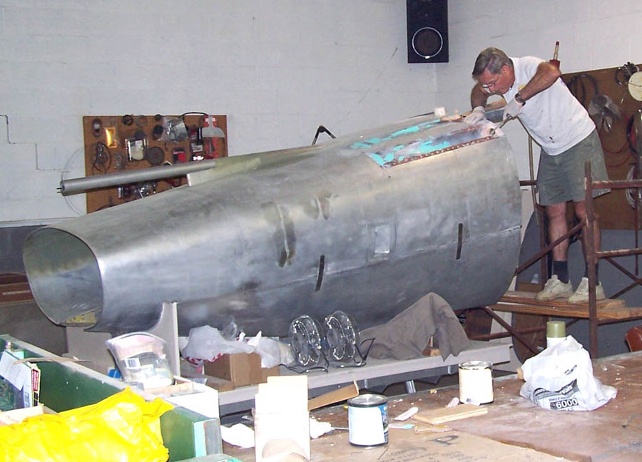 |
Steve's work cart 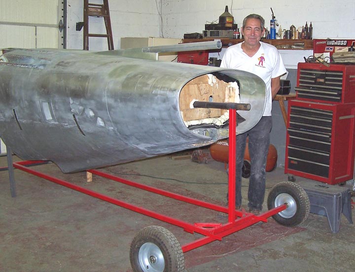 |
Once the front fuselage frames, the top and bottom skin plates, and the inspection panels were completed, Steve and I flipped the fuselage upside-down. Actually, the word "flipped" doesn't begin to describe the process -- which involved a hoist and a lot of nervousness about damaging all the work we had done. As you can tell by looking at Figure 1, cell 01, we managed the job successfully ... but working on the bottom details such as the gun blast panels and gun ports required a ladder at this point. Clearly, that solution was too awkward and too likely to lead to accidents. (Check the Fuselage Part 1 link to see how we constructed this "1:1-scale model" up to this point.)
Working on the details such as the gun ports required easier access than was possible on a ladder. Therefore, Steve built a small scaffold to provide a more stable work environment. Figure 1, cell 02, shows that I now had a much better platform to work on the gun blast panels and the gun sleeves. (Check out the "Gun blast panels" and the "Guns" options on the restoration menu to see how those components were made.)
Note: You can enlarge the pictures by clicking on them.
|
Gun port work |
Detail work |
Steve's work cart |
The scaffolding solution shown in Figure 1, cell 02, worked fine for some of the work. However, if I decided to work on the top portion of the fuselage, the fuselage would have to be flipped over again -- a tough job that made damage to the already-comleted work an uncomforatble possibility. If we could rotate the fuselage along its longitudinal axis, all portions would be easily accessible for all the subsequent heavy-duty sanding, detailing, and painting. Steve's solution was to make a few plywood formers to fit inside the intake segment, drill holes through the center of those formers, and place a 2-inch rod through the formers to fit into a frame that would let us rotate the fuselage around its axis. Figure 1, Cell 03, shows the results of his engineering effort ... Note the use "hard foam" to ensure that the frames would not slide and the use of heavy-duty black plastic sheet between the frames and the intake's interior to ensure that the (temporary) frames could be removed easily when all work was completed. (Incidentally, also note the perfect fit of the PVC-pipe pitot segment and the fiberglass gun blast panels. And, yes, the new aluminum is a bit scuffed and there's some Bondo patching here and there. Dimples, dings, and scratches happen ... and new aluminum needs to be lightly sanded to help the paint adhere later.)
While we were working on the final details of the fuselage front end, it was time to start working on the cockpit section of the fuselage. I had all the skin panel and access door tracings for this section, so the first order of business was to lay out the tracings and start transferring them to aluminum. Figure 2, cell 01, shows that the process is well under way. The kick steps are done at this point -- note the tracings in the upper right-hand corner. Two small skin panel sections have already been taped to aluminum sheets to be cut later. (Because the panel tracing collection took up a lot of floor space, I had to get on a ladder to take this picture.)
Figure 2, cell 02, shows that detailed planning and documentation are part of the project. (I spent a lot more time with Microsoft PowerPoint than I really wanted to, but the effort does pay off by making it possible to do some serious preliminary work.) In any case, the LOX (Liquid Oxygen) access door details show up well in this picture. (Note: You can see that I have already made a rough cut of this access door if you take a look at the upper right-hand corner of the picture shown in Figure 2, cell 01.)
Pete Felts, who has been a terrific source for answers to all sorts of questions
about the F-100 made the following comments after I had sent him a copy of the
picture shown in Figure 2, cell 02:
That's the LOX (Liquid Oxygen)
servicing door. If you look down at the bottom of the fuselage, just forward of that
grounding decal, there should be a small hole with threads on it. (That�s the LOX
overflow port.) We had the sheet metal guys in Vietnam build a round cylinder that
would hold four beer cans, so when we serviced LOX, we would put the cans in the
container while servicing. When the LOX overflowed, we had ice-cold beer. Worked for
sodas as well, but we just didn't drink too many sodas.
|
Skin panel tracings 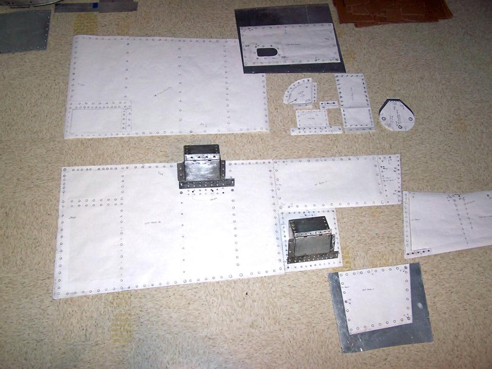 |
LOX access door 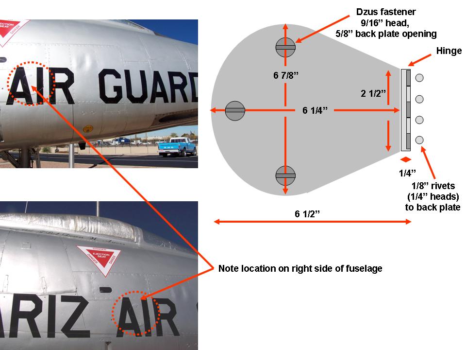 |
Rescue access panel  |
Figure 2, cell 03, shows the details of the rescue access door panels. Fortunately, I did not have to make one of those ... it turned out that several general aviation aircraft use oil inspection panels that are very similar to the access panel you see here. New ones turned out to be very expensive, so I spent some time looking at aircraft salvage sites.
Pete Felts supplied the following information about the the rescue access
door in Figure 2, cell 03:
Inside the rescue
access panel is a lanyard about 6' long with a "T" handle. You would open
the door and grab the handle, start pulling the lanyard, and run like hell
away from the fuselage while you were pulling that lanyard. When you got
to the end of the lanyard, you would blow the canopy off.
Tackling such a big project can be daunting ... but if you do the small stuff first, you get lots of satisfaction from seeing some parts and pieces completed. Figure 3, cell 01, shows the pieces that would come together to make one of the more complex panels located below the canopy and just above the LOX service door. I thought that the glass insert in the panel was some sort of inspection port, but
Pete Felts quickly set me straight after I emailed him a question about it:One of the trickier parts of producting the refueling boom light panel was cutting the lens. Steve and I had visited several glass shops, but none wanted to cut the lens for us. Steve finally suggested that we should cut the lens from a piece of plastic scrap. Figure 3, cell 02 shows Steve at work ...
|
Preliminary work 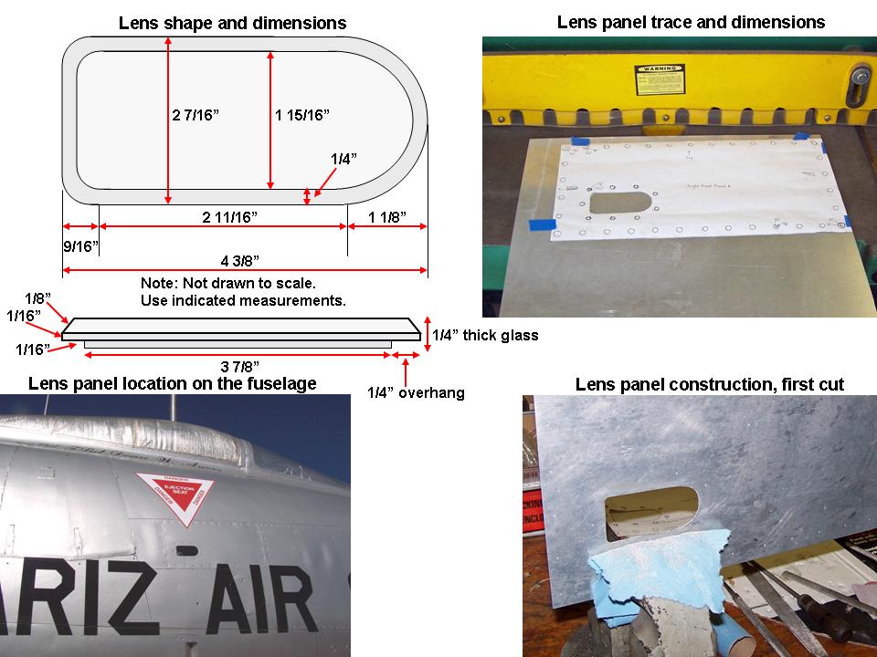 |
Cutting the lens 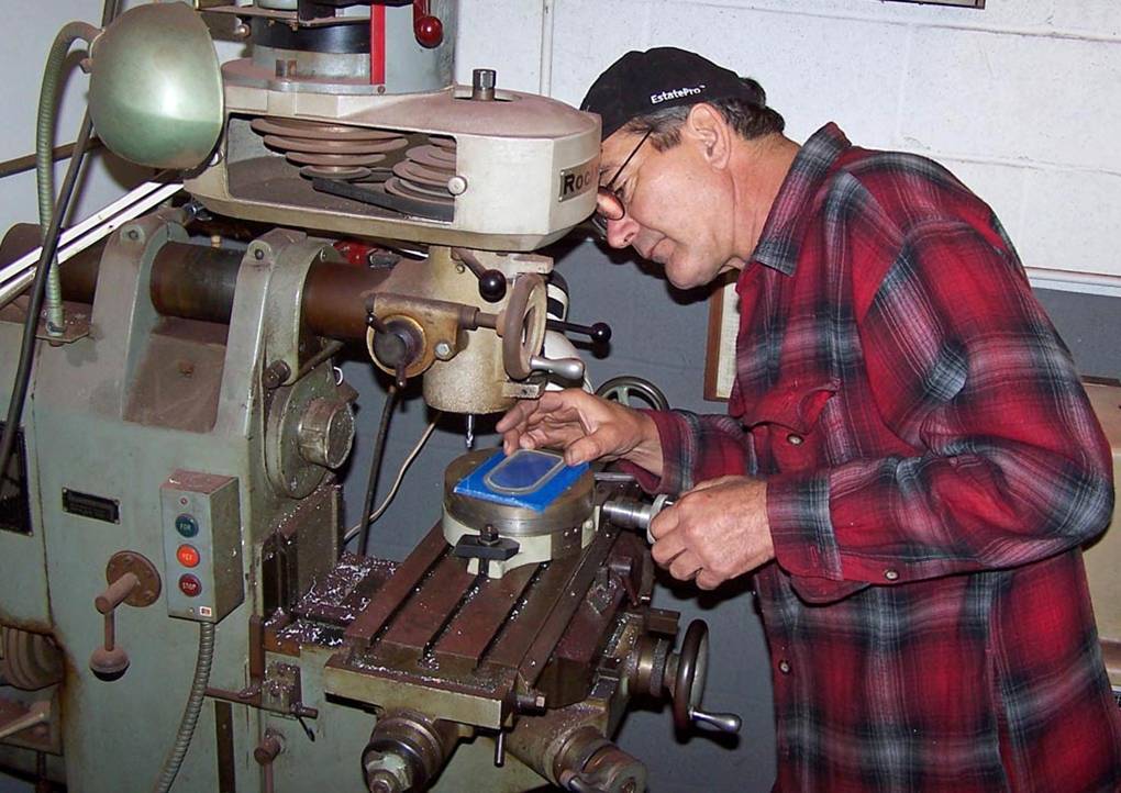 |
Completed pieces  |
Before any panels could be cut, the frame has to be ready to receive them. The cockpit simulator segment turned out to be an excellent frame rib template and it matched the detailed drawings I had bought from the Smithsonian.
Figure 4, cell 01, shows a composite picture that illustrates the frame components. The upper left-hand picture shows a stretching tool that is used to curve the metal section that has already been bent in a bending tool. A completed frame rib lies just behind the stretching tool. The gray panels are acid-free mat board used to provide a clean-looking liner. The remaining two pictures within the composite show the left-side framework segments below the cockpit.
Figure 4, cell 2, shows another composite picture that illustrates the kick-step design, the paper cut-outs based on tracings from a real F-100D, the completed kick-steps, and the lower kick-step panel. (The other kick-step panel you see is a "reject" that didn't have a proper fit around the kick-step ... I tried to work too fast and cut too much.)
Figure 4, cell 3, shows the lower kick-steps within the completed kick-step panel. The next panel, traced on paper, is in position for final measuring and cutting. (Two other small panels have been completed, too ... one is located to the right of the paper panel and one is located to the right of the just-completed kick-step panel.)
|
Frame construction 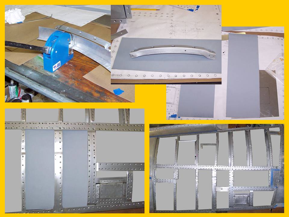 |
Kick-step construction 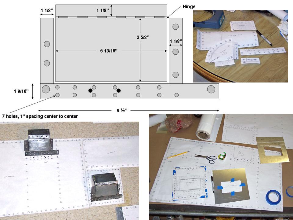 |
Kick-steps and panels 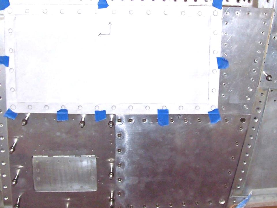 |
As this major "modeling" project moves forward, I will post pictures of the progress we're making. I may not be able to have a real F-100 ... but a properly contructed full-scale model will not be distinguishable from the real thing. Stay tuned.
While the rebuilding and restoring efforts are important, please remember that the main focus of the F-100 project is its database. If you can supply stories and pictures that reflect your experience with the Hun, please do so. (You can click on the Contact me link to send me an email.) The objective is to develop a very comprehensive personal history of the Hun and of the people who flew and maintained her. You and the Hun deserve to be remembered in your own words.
If you want to return to the home page, you can either click on the
Home link shown here or by clicking on the Home link shown on left side of your screen. (You can also use any of the navigation bar links shown on the bottom of the screen to move around this website.)