|
Skin dimpling 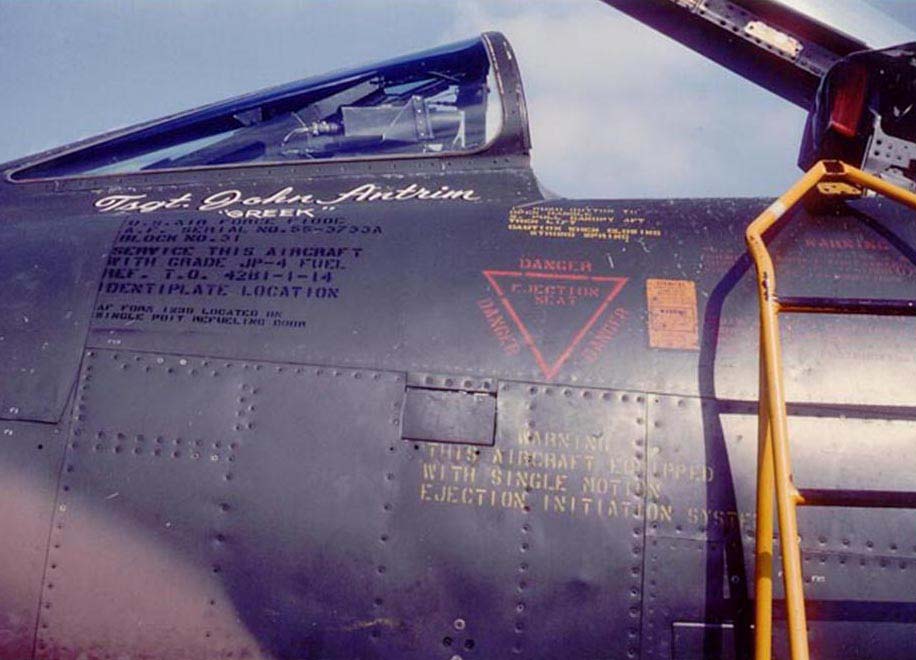 |
More skin dimpling 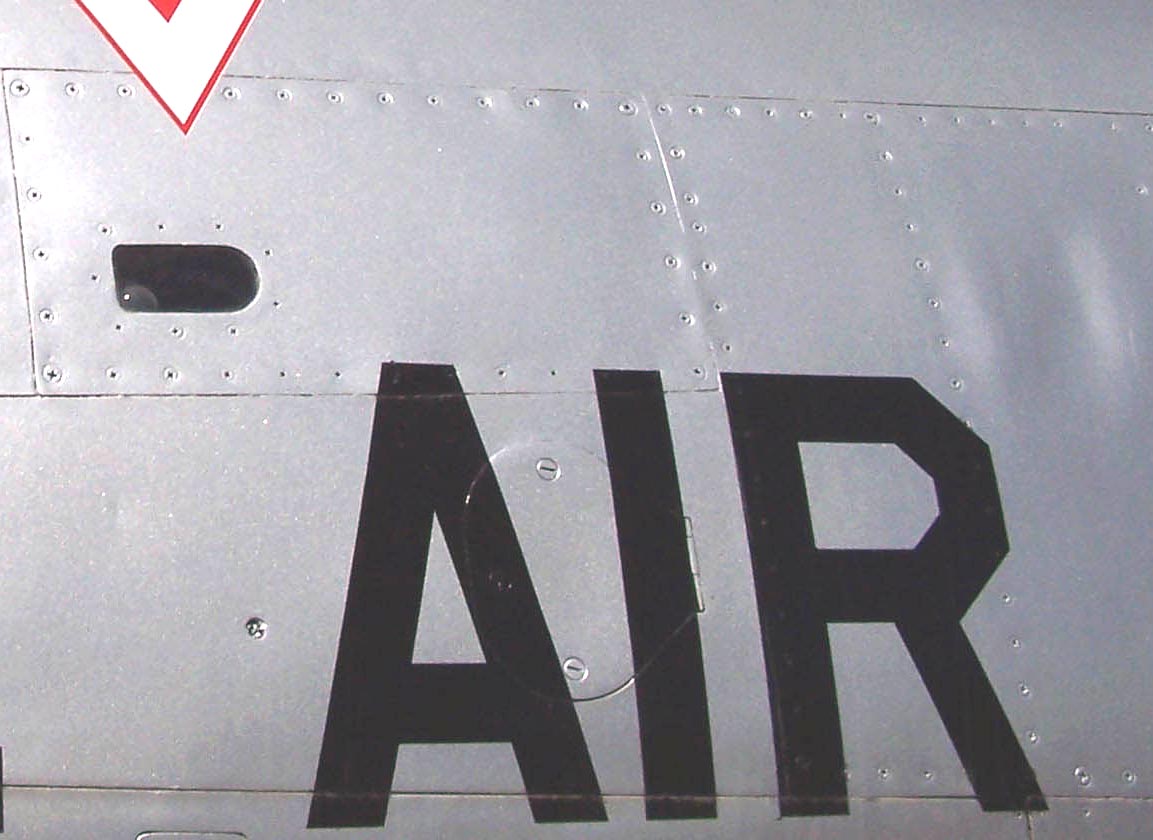 |
New skin panel work 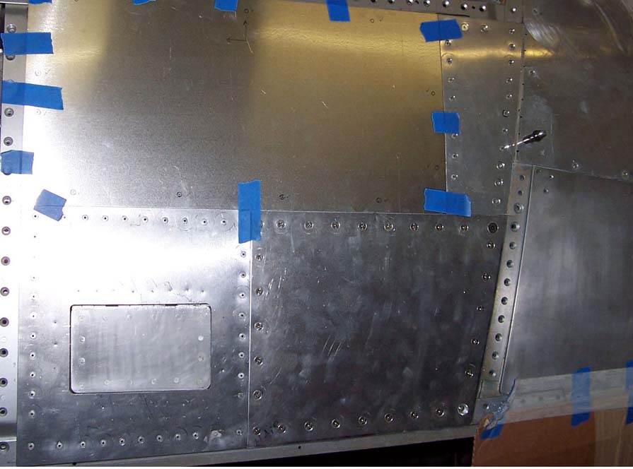 |
After the frame was ready to receive the skin panels, it was time to manufacture and install those panels.
(You can see the frame elements at the bottom of the Fuselage Part 2 page.)Cutting the skin panels is a matter of placing the panel tracings on an appropriate sheet of aluminum and cutting the aluminum to match that tracing. The new aluminum panel is then held in place with tape to see if it fits the frame exactly. If it does, the fastener holes are marked, drilled, and de-burred. Next, the new panel is fastened to the frame with clecos to check all the hole alignments before the holes are "seated" to make sure that the fasteners -- usually, rivets or Phillips head screws -- will be properly counter-sunk to match the panel surface. Finally, the fasteners are applied.
After we attached the first few fasteners, we noticed that the surface dimpled slightly. Actually, that's what the real deal does, too. Figure 1, cell 01, shows the typical dimpling around rivets and screws. (I took this "detail" picture of 56-3081 at the Missouri Air National Guard base in St. Louis, MO, in 1977. You can check out the story of the visit to that base by selecting the database option and then search for Peter Rob on the contributor list. Scroll down until you see that story.)
Figure 1, cell 02 shows a section of F-100D skin of an Arizona Air Guard F-100D, 56-3055, which shows similar dimpling. (I took that photo in February, 2007, at the Arizona Air National Guard base in Tucson, AZ. Thanks to Al "Smitty" Smith, who took me to visit that Guard unit.)
Figure 1, cell 03, shows a section of my F-100D's skin panels in various stages of completion. The rivets you see are cherry rivets, so I'll still have to fill in the small center holes, then sand them smooth to simulate "real" flush rivets. The finger prints and smudges will be cleaned off when I get ready for painting, so that's a long way off. I still have to drill the fastener holes into the taped piece and then do the whole de-burring and "seating" deal. According to the pictures I have, the taped skin plate you see in the picture must be attached to the frame with Phillips screws, so we'll have to put in the back plates before that can happen.
Note: You can enlarge the pictures by clicking on them. Then maximize the window to get an even closer look.
|
Skin dimpling |
More skin dimpling |
New skin panel work |
Perhaps one detail that stands out when you look at Figure 1, cell 03, is that the new panel fit is very tight, even tighter than the panel fit you see in Figure 1, cells 01 and 02. That's more evidence that Steve Rettell taught me well ... and that I really want this "model" to be first-class. I do have to confess that I had to re-cut and re-drill two of the panels -- one of them three times -- before I was satisfied with the fit. It's better to buy more aluminum sheet than to agonize over flaws later. In any case, as the F-100 project continues, the construction results continue to improve -- especially since Steve is always there to bail me out of whatever trouble I get into.
Comment by Pete Felts:
When working on the Huns, especially older ones, you would often see cracks
in a lot of the screw holes, especially on the 0.022 panels. Also, there is a
certain amount of spacing around the panels because they have a tendency to
shrink and contract at ground level and at altitude. In addition, the structure
of most supersonic fighters is flexible to compensate for "G" forces. The next
time you get close to a display model, check the fuselage just aft and below
the RAT (Ram Air Turbine) and you will see a long heavy strip of metal on both
sides. That strip was put there when we found that the fuselage was cracking
and those "security strips" were the fix for that. Also, look under the wings
the next time your around a static display and you will see the same kind of
strips close to the Main Strut Boss. (We were getting cracks in that area from
landing stress.) We had two choices, replace the wings or do stress relief by
drilling out the stress points and strengthening the area with straps. We went
with the straps.
One of life's rules seems to be that the things that seem simple often turn out to be major challenges. Attaching the panels to the frame provides a perfect example of that rule. I had perfect panel tracings that showed the exact location and size of each fastener -- Phillips screw, rivet, or Dzus fastener. Each panel tracing was taped to its frame section and that frame section was marked to match its tracing. I assumed that this process would ensure that holes drilled in the panel would match the holes drilled in the frame section. (After all, the thin paper had been stretched over the original aircraft's curved panels, so the paper tracing should match the curvature perfectly.)
Actually, the just-decribed procedure worked well for the small panels you see in Figure 1, cell 03 ... but the larger panels were another story. The panel you see taped in place with blue painter's tape in Figure 1, cell 03, had already been re-cut several times to yield a perfect fit -- but the holes I drilled later failed to line up exactly with the holes in its frame section. Steve Rettell came to the rescue by handing me a tool known as a "hole finder." You see an example of such a tool in the center portion of the photo in Figure 2, cell 01. The tool is basically a set of flat forceps with a nib on one side and a drill bit guide on the other side. (Steve made the larger hole finder you see that the top of the picture to let us reach across even the largest panels.)
Figure 2, cell 02 shows how the hole finder tool is used: Slide the "nib" portion of the tool between the panel and the frame until the nib clicks into place in the frame hole, place the drill bit in the drill bit guide that is now located precisely over the nib on the other side of the panel and drill the hole.
Note: You can enlarge the pictures by clicking on them.
|
Hole finder tools 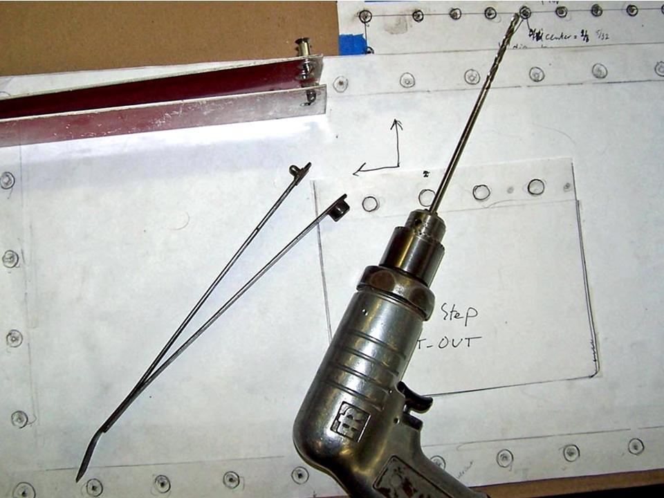 |
Using the hole finder 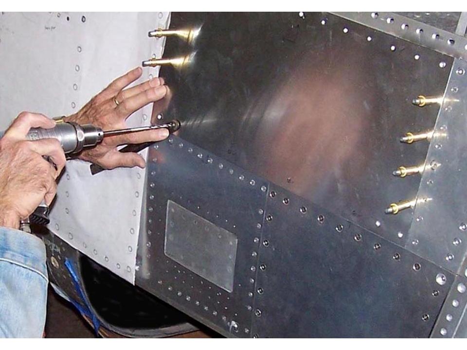 |
Completed panel section 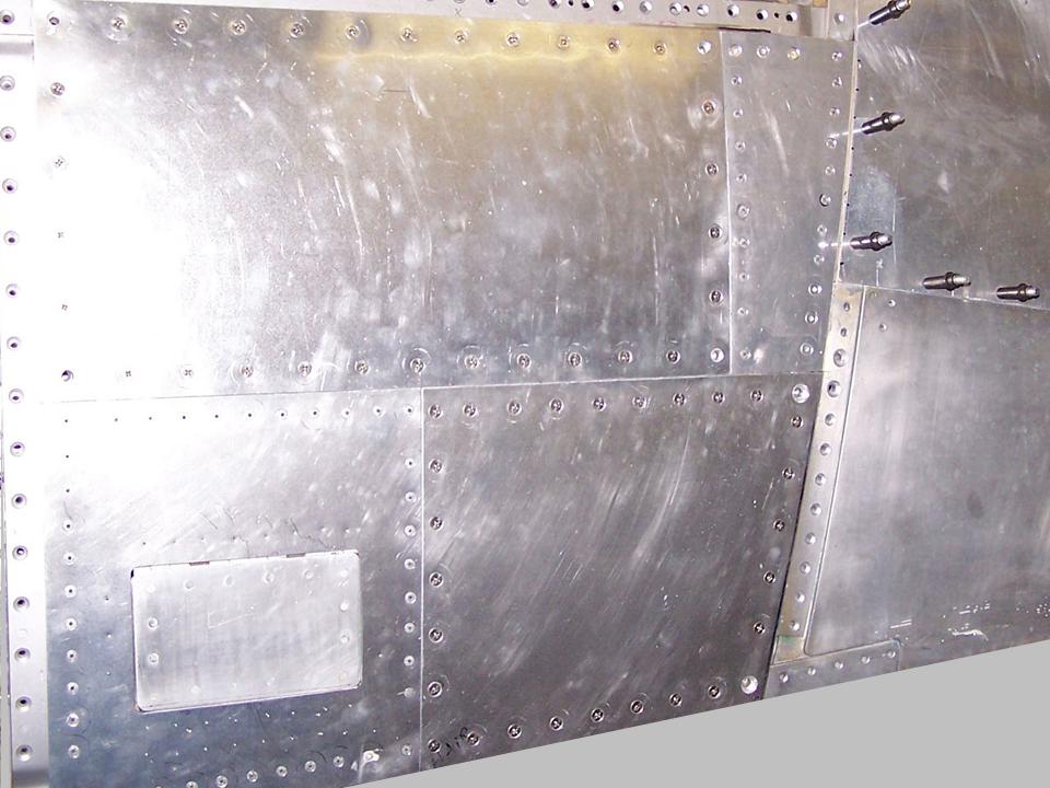 |
Figure 3, cell 01 shows the panel cut-out for the the upper kick-step. The paper panel beneath the aluminum sheet was the template for a thin cardboard template that was used to check the panel's fit before the aluminum was cut. Even with that much measuring and fitting, the panel had to be cut twice. (It's amazing how much "give" there is when you start bending aluminum.) The first panel cut made a good template for the final panel cut, which gave a nice, tight fit. Fortunately, the initial panel was sufficiently large to let me cut two small bottom panels, so the waste was kept to a minimum.
After the panel was completed, all the fastener holes were marked with Steve's hole finder tool and then Steve used the drill press to drill the remaining fastener holes. (This panel required Phillips Head screws to match the close-up photos of the panel -- see Figure 1, cell 01.) It took two of us to do the drilling ... the panel was too large for a single individual to hold it in place. After the drilling was done, I spent a few hours de-burring the fastener holes and then the panel was attached to the fuselage frame with clecos -- see Figure 3, cell 02.
Note: You can enlarge the pictures by clicking on them.
|
Upper kick-step Panel 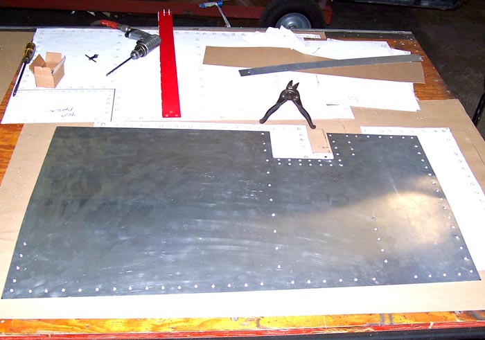 |
Fastened Panel 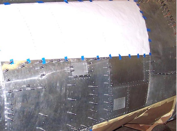 |
Cutting the Next Panel 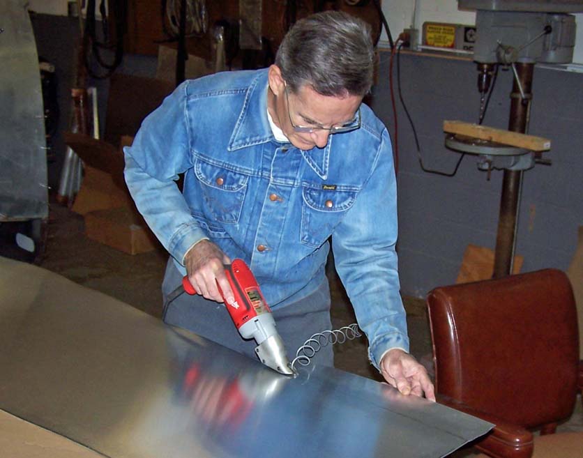 |
Given its size, the long panel below the canopy section was a particular challenge. I had already found out the hard way that cutting the aluminum based on a large -- and very flexible -- paper tracing tended to yield a poor fit. Therefore, the paper tracing became the basis for a thin cardboard template that was then attached to the frame. (An imprecise fit is much easier to correct with a cardboard template.)
After the template fit was judged to be acceptable, I taped it to the aluminum sheet to trace it. After the tracing was completed, I cut the aluminum with Steve's electric shears. (See Figure 3, cell 03. The large bench shears couldn't do the job, because the panel lines on this piece are slightly curved.) I purposely kept the shears well outside the trace line to make sure I had a sufficient margin for final trimming to produce a good fit. (You can always shave off some aluminum, but it's not practical to try to add aluminum.)
Figure 4, cell 01, shows just a section of the panel you saw in its paper version in Figure 3, cell 02, and as a first cut in Figure 3, cell 03. At this point, most of the holes had been drilled and de-burred and the panel was held to the frame with clecos. Unfortunately, bending the metal panel against the curved frame segment produced some distortion at the panel edges, thus requiring additional trimming. "Patience" became a major virtue. The process seemed simple enough: Hold the piece in place with clecos, mark the panel for trimming with a scribing tool, and then take the panel down again to do some more trimming. (Initial trimming was done with a sharp set of shears and subsequent trimming required the use of a good set of files. Naturally, the trimming process had to be repeated for each of the four panel sides.)
The picture you see in Figure 4, cell 01, was taken after the third trimming session. Each trimming session required the removal of all the clecos, a filing session, and the re-attachment of the panel through the re-insertion of all the clecos. (Attaching the panel with only a few clecos would not work, since "oil canning" would become a major problem.) Removing and re-inserting hundreds of clecos at a time proved to be a fine way to produce major cramps in my fingers and hands ... but the process is guaranteed to give you a strong grip!)
Steve kept looking at my trimming efforts and finally said: "This is just a suggestion ... but if you take the screws and clecos out of the panels below this piece and then slide it underneath those panels, you'll have a perfect cut line." DUH! (Steve is obviously much smarter than I am ...) Anyway, that's how the final trimming was done, one panel side at a time.
Note: You can enlarge the pictures by clicking on them.
|
Clecos, Lots of Clecos 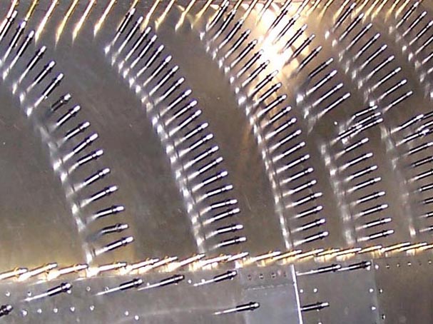 |
Rescue access door 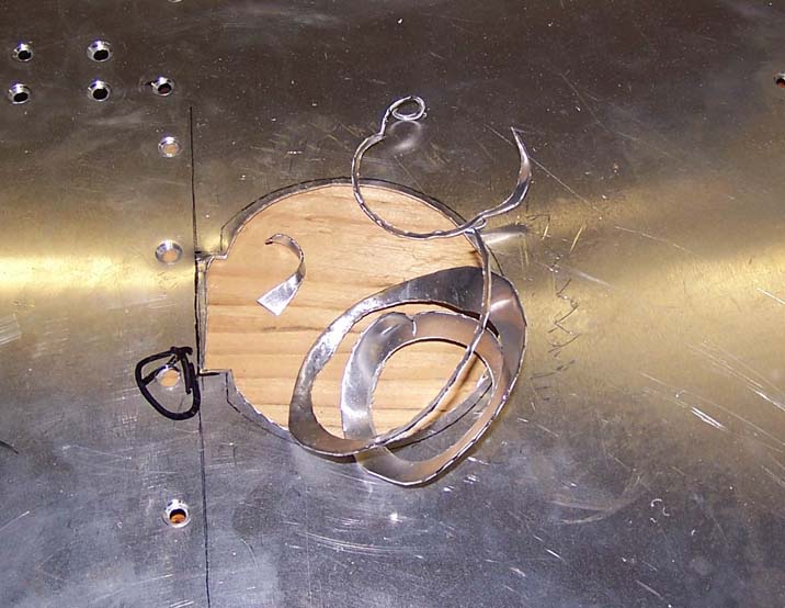 |
Rescue door parts 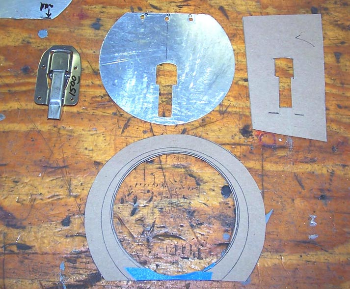 |
Making a perfect skin panel is tough enough without adding complications such as access panels. Making the rescue access panel I showed on the Fuselage, Part 2 page turned out to be a real bear for several reasons. First, the cut-out is located well inside a panel that is slightly curved in two directions. Using a key-hole cutter on a curved surface is an adventure. (No, you can't bend the panel after you cut a hole, because the hole will distort the bending stresses.) Second, using metal shears to cut close the the cut-line requires a fine touch. Third, after spending many hours on making a good skin panel, caution is a good thing ... lesson 1: don't get too close to the cut line! Using a set of files is the better bet for a close fit. Figure 4, cell 02 shows the first cut ... a bit rough at this point, but some hours with files will do wonders.
Once the hole is cut and shaped perfectly, it's time to make an access door that fits the hole precisely. Figure 4, cell 03, shows the start of that process. The cardboard piece is the backing plate for the rescue door. (Gene Sloan, a much-valued member of EAA -- Experimental Aircraft Association -- chapter 419, donated the latch ... he had a spare of one he used on his Thorp 18, an experimental aircraft.) The cut-out for the latch was first made in cardboard to ensure a perfect fit for the latch -- once the fit was correct, the cardboard template was used a the basis for the metal access door cut-out.)
Figure 5, cell 01 shows the results of several weeks' worth of work. Steve and I wound up spending a lot of hours fitting, drilling, clecoing, and riveting. And, yes, I wound up cutting the recue access door four (!) times before I was satisfied with the fit. I make lots of perfectly good scrap that way ... and Steve sells the scrap to buy feed for his chickens, so scrap is not a bad problem.
Incidentally, the first rescue door took me just over five hours to make -- including the latch cut-out. The fourth rescue door took me just over two hours to make, thus illustrating that experience yields some benefits. (I also managaged to demonstrate remarkable healing power after I lost control over a piece of aluminum that did a fine job slicing into a finger and an arm. Some duct tape helped keep the wound edges together long enough to cure the problem after a few days. As I used to tell my son, "If you're going to be stupid, you'd better be tough.")
Note: You can enlarge the pictures by clicking on them. (Maximizing the window will show you even more detail ...)
Figure 5, cell 02 shows the nearly-completed panel with its rescue access door. The section underneath the access door was made of a perfectly-sized saurkraut can. That section contains the T-handle to the lanyard that blows the canopy if neither the pilot nor the rescue crew can open the canopy of a crashed aircraft. (The interior section was painted "interior green" ... the plastic you see in the picture ensured that the paint spray did not contaminate the skin panel.)
Figure 5, cell 03 shows the completed panel. I will apply the rescue arrow pointing to the rescue door much later ... no sense in doing the final clean-up and paint work until the remaining fuselage panels are done. It's just too easy to damage a fine paint job ...
Note: You can enlarge the pictures by clicking on them.
|
Rescue door fitting 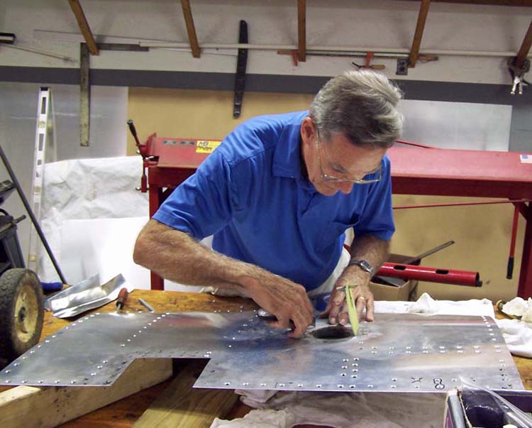 |
Rescue access door 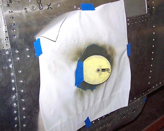 |
Nearly completed panel 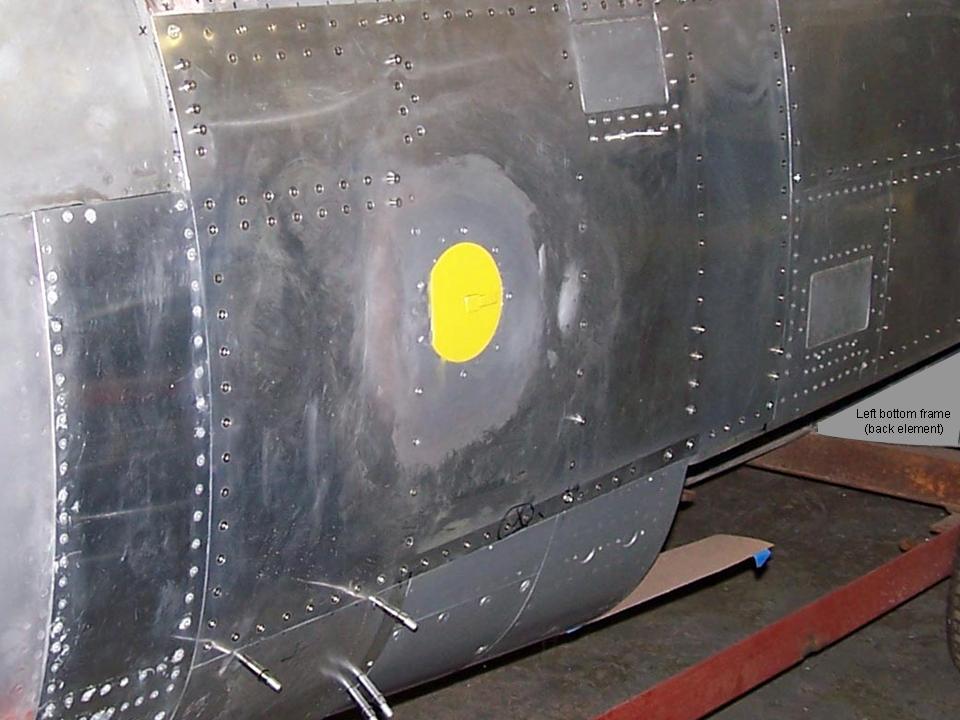 |
As this major "modeling" project moves forward, I will post pictures of the progress we're making. I may not be able to have a real F-100 ... but a properly contructed full-scale model will not be distinguishable from the real thing. Stay tuned.
While the rebuilding and restoring efforts are important, please remember that the main focus of the F-100 project is its database. If you can supply stories and pictures that reflect your experience with the Hun, please do so. (You can click on the Contact me link to send me an email.) The objective is to develop a very comprehensive personal history of the Hun and of the people who flew and maintained her. You and the Hun deserve to be remembered in your own words.
If you want to return to the home page, you can either click on the
Home link shown here or by clicking on the Home link shown on left side of your screen. (You can also use any of the navigation bar links shown on the bottom of the screen to move around this website.)