|
Cast of characters 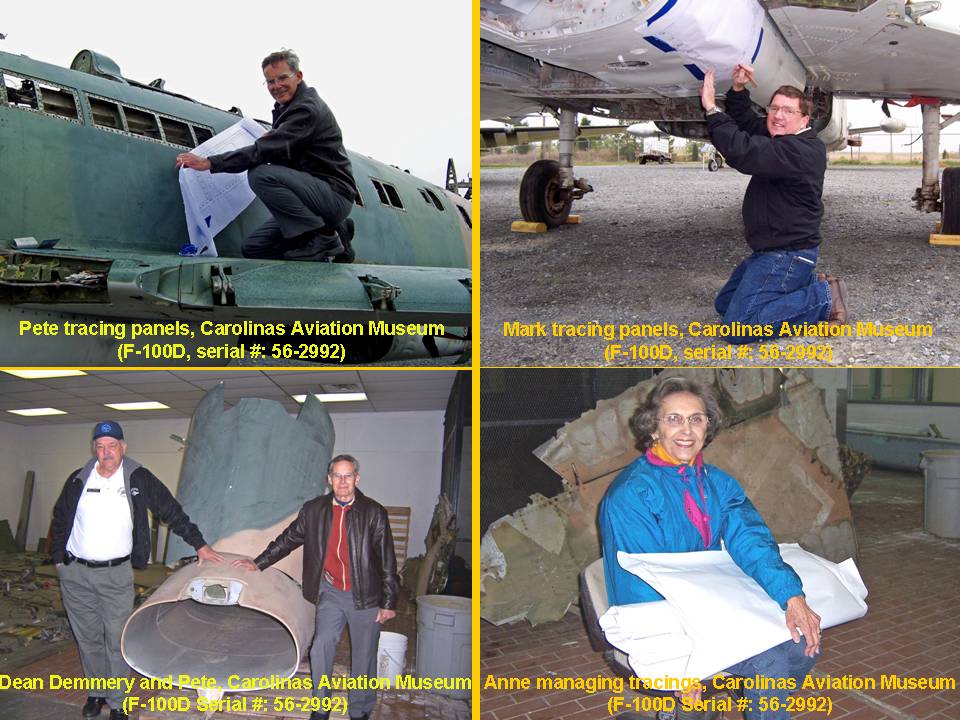 |
Skin panels 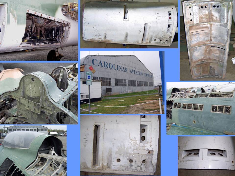 |
Tracings 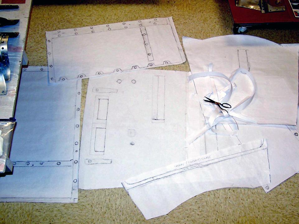 |
Getting the full-size F-100D "model" right means finding places that have the real aircraft and then finding good people who will let you climb all over their treasures so that you can trace the skin panels to make very accurate panel copies. (Not to mention the fact that proper documentation requires that you record all all sorts of parts and pieces with a digital camera. Acccurate measurements, too, are part of the documentation game.)
Fortunately, Mark Brown -- a close friend we consider to be a part of our family -- lives in Charlotte, NC. It turns out that Charlotte is also the home of the Carolina Aviation Museum, which had acquired an F-100D that was in the early stages of its restoration process. Better yet, Mark introduced me to a really fine gentleman named Dean S. Demmery, who manages the Carolinas Aviation Museum. After we explained the nuts and bolts of the F-100 project, Dean gave us free and complete access to his F-100D. Mark and I spent the better part of a day tracing skin panels, taking pictures, and taking numerous notes. (We also measured all parts we did not trace.)
Figure 1, cell 01 shows the cast of characters involved in the documentation process. When we were done with the F-100D parked outside, Dean took us on a tour of his extensive warehouse facilities. (It was a cold and drizzly day, so Anne, my wife and best friend, spent most of the time indoors looking at the exhibits and talking to the volunteers who help make the museum a success.)
Cell 02 shows some of the F-100D pieces that Dean had stored inside. These pieces, too, were traced, measured, and recorded.
Cell 03 shows a few of the cleaned up paper tracings in my F-100 building.
Note: You can enlarge the pictures by clicking on them. Many of the pictures can be enlarged some more by placing the cursor on them and clicking again. Then maximize the window to get an even closer look.
|
Cast of characters |
Skin panels |
Tracings |
After returning home, the skin panel tracings were laid out in the F-100 building to be cleaned up and cut along the panel lines. I then began the tedious work of transferring the paper tracings to thin cardboard. Each cardboard copy became the template for the actual skin panel. Figure 2, cell 01, shows a cardboard template attached to the fuselage frame. (The frame is made to match the template to ensure that there won't be any surprises when the aluminum panel is attached to the frame. Since you won't be able to see the frame anyway, it is not necessary to have an exact copy of the real aircraft frame ... which we would not have access to unless we could find a completely stripped F-100D.)
Figure 2, cell 02, shows the transformation from paper tracing to cardboard template to aluminum panel. (This panel happens to be located on the lower fuselage front section.) Cell 03, shows a newly-cut skin panel in place.
There is still a lot of work to be done. For example, the Dzus fastener holes have not yet been made and the back plates still have to be attached. But the most important work has been done -- the skin panel is exactly the right size and it's in the exactly correct place. Just a few more years of work to go ...
Note: You can enlarge the pictures by clicking on them. Many of the pictures can be enlarged some more by placing the cursor on them and clicking again. Then maximize the window to get an even closer look.
|
Cardboard template 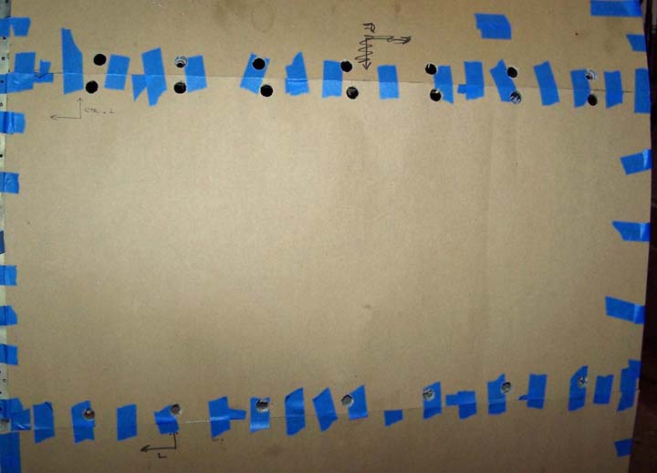 |
Transformation 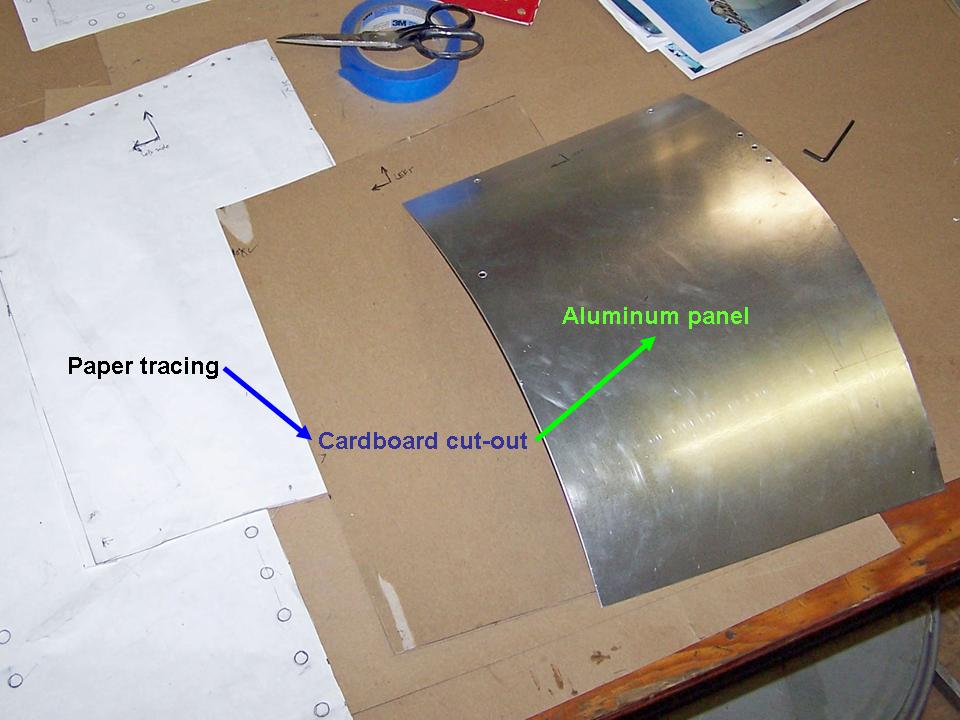 |
New aluminum panel 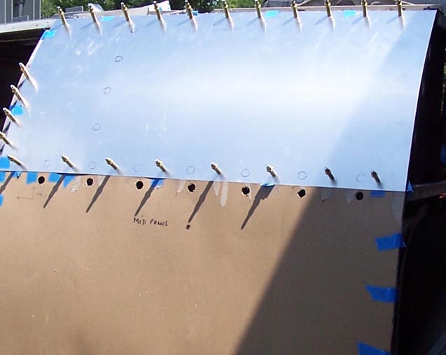 |
Making the Dzus fastener holes turned out to be a bigger challenge than we had anticipated. I had successfully cut and formed the back skin panels and I had marked the Dzus fastener holes on the aluminum panels to match the tracings I had made at the Carolinas Aviation Museum. (The proper curvature was made by bending the newly-cut aluminum panel over a large -- empty -- acetylene tank. Sometimes, simple tools and procedures do the job just fine!)
Attaching the panels with Dzus fasteners seemed cumbersome, since the underlying home-made frame did not have the proper back plates for such fasteners. Because there was nothing behind the panels other than the frame, there would be no point in attaching the panels with functioning Dzus fasteners. Given the fact that there was no need to open and close the panels as would be done on a real F-100, I proposed that we simply cut the heads off the newly-bought Dzus fasteners and then insert those heads into properly drilled and seated holes to match the Dzus flanges. (The panels will be attached with rivets ...) Unfortunately, that decision required very precise drilling and counter-sinking. Figure 3, cell 01, shows a few early attempts and the -- finally -- successful procedure. After Steve had perfected the proper procedure, he drilled and seated the Dzus fastener holes, as you can see in the lower portion of cell 01. Cell 02 shows a section of two of the skin panels with with the correctly-spaced, cut, and counter-sunk Dzus fastener holes. Cell 03 shows the three top panels ready for the cut Dzus heads. (The lower panel you see in cell 03 will be attached to the fuselage frame with Phillips screws to match the real F-100's panel.)
Note: You can enlarge the pictures by clicking on them. Many of the pictures can be enlarged some more by placing the cursor on them and clicking again. Then maximize the window to get an even closer look.
|
Practice 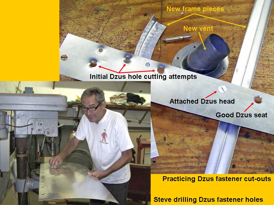 |
Completed holes 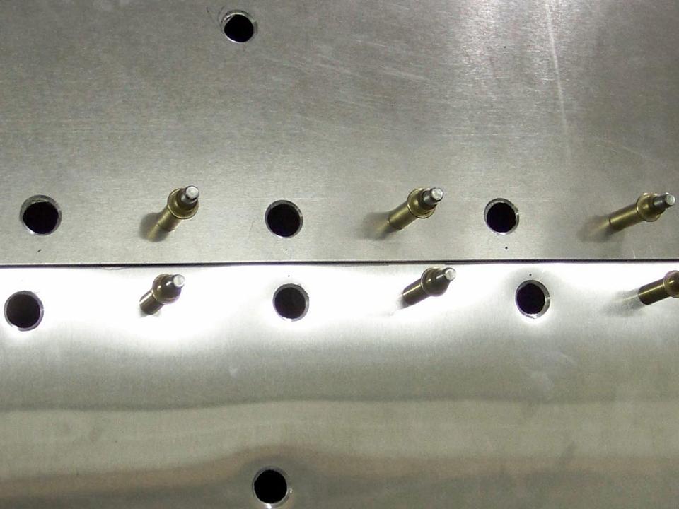 |
Completed panels 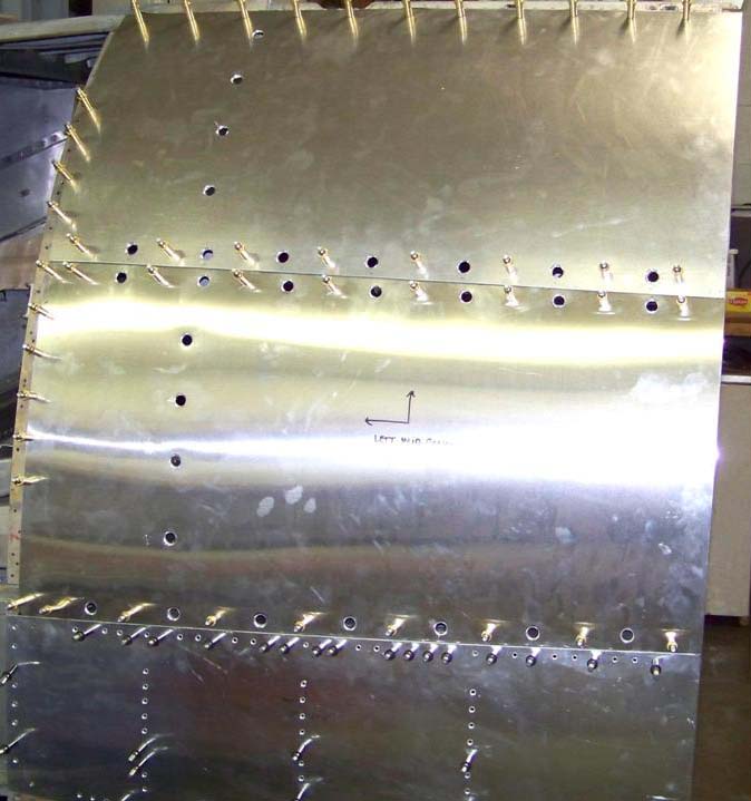 |
As you examine Figure 3, cell 03 closely, you'll see that the back portions of the skin plates are still "free-floating" at this point. That's because we have not yet made the bulkhead for this back section.
Because the back end of the fuselage we had constructed thus far had the correct size and shape, we traced that section again to begin the bulkhead building process. (I had bought the blueprints you see in Figure 4, cell 01, from the Smithsonian in 2007, so those blueprints were matched against the completed fuselage section I had traced on plywood.) The two pictures shown on the left side of cell 02 show some of the work done on the new plywood bulkhead piece. The picture shown on the right side of cell 02 shows how the 2-inch wide and 1/8-inch thick aluminum anchor strip was attached to the plywood.
Note: You can enlarge the pictures by clicking on them. Many of the pictures can be enlarged some more by placing the cursor on them and clicking again. Then maximize the window to get an even closer look.
|
Blueprints 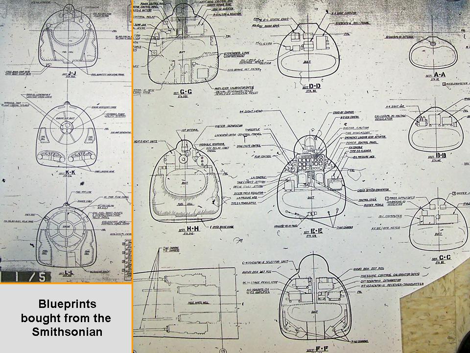 |
Bulkhead work 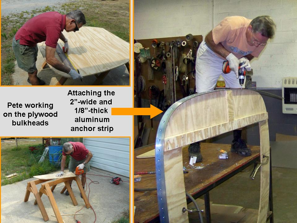 |
Completed bulkhead 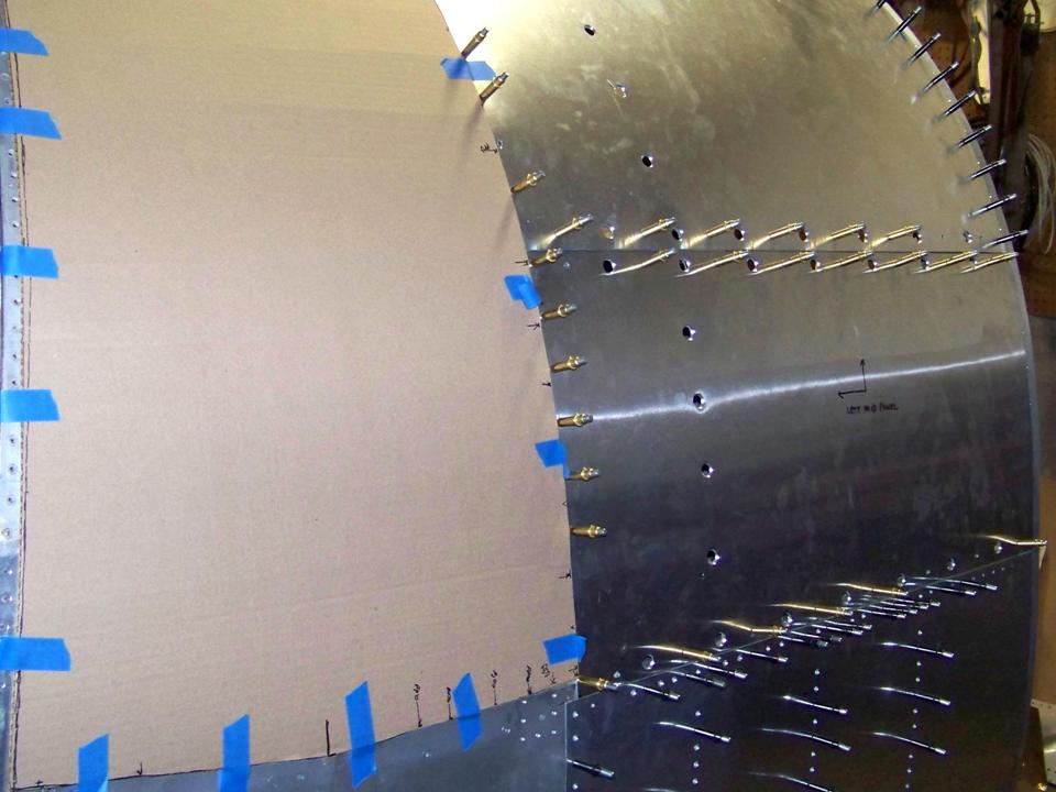 |
Figure 4, cell 03 shows the top panel attached -- with clecos -- to the newly-completed bulkhead's metal anchor strip. (The new bulkhead has been bolted to the preceding fuselage segment. All of the back panel pieces you see in cell 03 will be riveted to this anchor strip ... which will also serve as the anchor point for the next set of formers and stringers that will be connected to the next bulkhead.) At this point, the next bulkhead section has already been cut and shaped, so there is a lot of progress to point to.
Incidentally, as you take a look at Figure 4, cell 03, note that the ammo bay door has been modeled in cardboard to become the template for the metal version. At this point, I don't have the actual tracing, but the cardboard version should be the correct size and shape, based on the space remaining between the already-completed metal skin plates. In any case, Pete Felts volunteered to get the actual ammo bay doors traced so that I can verify the measurements and know precisely where the fasteners are located and what the fastener sizes are. (Pete Felts has made many fine story and photo contributions to the database portion of this project -- just check the database link on the left side of the screen and then do a search for his name after clicking on the first database option.)
As this major "modeling" project moves forward, I will post pictures of the progress we're making. I may not be able to have a real F-100 ... but a properly contructed full-scale model will not be distinguishable from the real thing. Stay tuned.
While the rebuilding and restoring efforts are important, please remember that the main focus of the F-100 project is its database. If you can supply stories and pictures that reflect your experience with the Hun, please do so. (You can click on the Contact me link to send me an email.) The objective is to develop a very comprehensive personal history of the Hun and of the people who flew and maintained her. You and the Hun deserve to be remembered in your own words.
If you want to return to the home page, you can either click on the
Home link shown here or by clicking on the Home link shown on left side of your screen. (You can also use any of the navigation bar links shown on the bottom of the screen to move around this website.)