|
Initial design 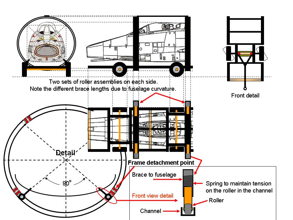 |
Design model 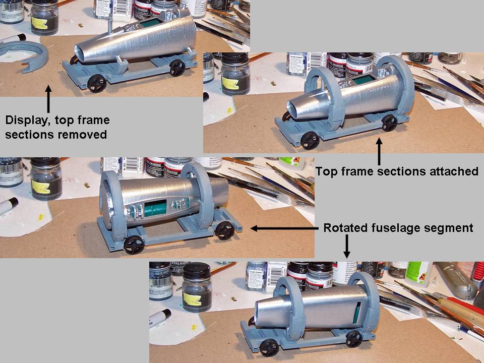 |
Modified design 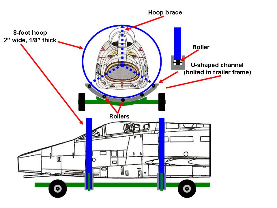 |
On the Fuselage Part 4 web page you saw the progress we made on the fuselage skin panels and on the bulkheads that shape the fuselage. You will see more of that progress on this web page.
We now turn our attention to the work that had to be done on the bottom of the joined fuselage pieces. On the F-100 Fuselage Part 2 web page, you saw the work we completed on the bottom of the fuselage just forward of the windscreen. (That section was only 8' 3" long and weighed a mere 500 pounds or so.) To make it easier to work on those bottom fuselage components, Steve had designed a structure that would let us rotate the forward fuselage section around an axle. (You saw that structure if you looked at the Fuselage part 2 web page, Figure 1, cell 03.)
Unfortunately, the joined fuselage section was over 20' long and weighed far too much to let us use the same rotation structure that had worked so well on the forward section. I spent a lot of time designing a rotating cage and even built a model of it to demonstrate its operation. The model worked fine, but it required some refinements.
Figure 1, cell 01 shows the initial rotating frame design. Basically, my design required a set of U-shaped steel hoops to be built into the trailer frame. The fuselage would have three 2" box steel supports, placed evenly at 120 degrees to distribute the weight evenly. Each support would have spring-loaded steel roller at its end and the steel rollers would fit into the channels formed by the U-shaped steel frame. Cell 02 shows the test model, which worked fine.
As usual, Steve's long record of hands-on engineering experience produced a better solution. He suggested a modification of the initial design to attach the hoops to the fuselage frame and then to let these hoops rotate in a steel cradle. Bingo ... a stronger and more stable solution. Cell 03 shows the modified design.
Note: You can enlarge the pictures by clicking on them. Many of the pictures can be enlarged some more by placing the cursor on them and clicking again. Then maximize the window to get an even closer look.
|
Initial design |
Design model |
Modified design |
The modified rotating frame design was a good solution. Unfortunately, even a good design may be introduced to real world realities. For example, finding a metal shop that could bend a heavy steel U-channel section to make a perfect 8'-diameter circle proved to be a real challenge. When I finally located such a shop, the charge per hoop would be $800 ... not a good solution. Steve came to the rescue again by pointing out that cattle hay feeders are 8' in diameter and that we could cut the required hoops from such feeders. Ah, yes, life is good ... especially when the feeders in question were on sale at the Co-op and Steve has a neighbor who had to pick up some supplies at the Co-op later that afternoon. That solved the transportation problem and the feeders were delivered without complications. (8' cattle feeders are BIG!)
Steve proceeded to cut the lower section from each of the feeders, thus leaving a set of circular frames. Given the construction of the feeders, those lower sections resembled a ladder curved into a perfect 8-foot circle. Therefore, we wound up with a wider-based -- and, therefore, more stable -- frame than the modified design showed. Steve also cut the outside steel hoop from the feeder, to be bolted into the center of the "ladders" ... thereby making the frame even stronger.
Figure 2, cells 01 and 02, show Steve making and then installing the rotating cage components and the fuselage supports. Note the plywood fuselage bulkhead and other fuselage frame components ... Steve managed to do all the welding without scorching anything. Cell 03 shows me working on the roll cage and, more important, it shows the completed rotor frame part of the roll cage.
Note: You can enlarge the pictures by clicking on them. Many of the pictures can be enlarged some more by placing the cursor on them and clicking again. Then maximize the window to get an even closer look.
|
Basic parts  |
Installation  |
Making progress 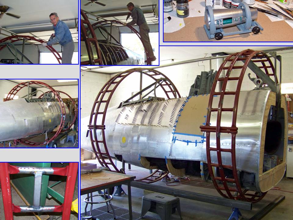 |
Even the best plans are subject to revision when they are implemented. The roll cage itself was a success, but there was a remaining problem. As you can tell by looking at Figure 1, cell 03, the modified design still shows the roll cage rotating inside a cradle ... and making such a cradle was well beyond our pay grade. First, we lacked the equipment required to curve heavy-duty angle iron into the required shape. Second, getting the cradle components made by a commercial outfit turned out to be a very expensive proposition. As usual, Steve's practical engineering knowledge saved the day during one of our lunch-time discussions. Why not simply get a solid phenolic cylinder and cut it into a set of eight 6-inch rollers, drill a core for each roller axle, and mount each roller on a steel bracket? The roll cage could then rotate over these rollers without requiring a cradle. Figure 3, cell 01 shows the final design modifications. Cell 02 shows a completed set of front and back rollers. (Note that the trailer frame has been completed and that the F-100 now sits on its trailer.)
The roll cage worked fine, but there still was a lot of work to be done on the fuselage sides. The composite picture in Figure 3, cell 03 shows the really fine -- hand-powered! -- bending and stretching tools that we used to make the internal frames for the side panels you see on the table. Note also that the cleco "forest" you can see on the panel below the cockpit in Figure 2, cell 03, has been replaced by rivets ... the result of many hours' worth of effort. (During that process, I managed to slip off the roll cage and hit the concrete floor. Amazingly, no bones were broken, but I did manage to add to the collection cuts and bruises that I have collected over several years' worth of F-100 work ... As I used to tell my son, "if you're going to be stupid, you'd better be tough!")
Note: You can enlarge the pictures by clicking on them. Many of the pictures can be enlarged some more by placing the cursor on them and clicking again. Then maximize the window to get an even closer look.
|
Final modification  |
Installed rollers  |
More panel work 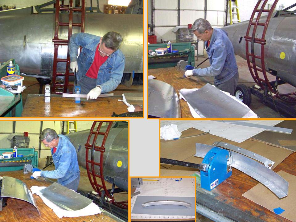 |
There is absolutely no way that building a really large-scale "model" of the F-100 can ever become routine. There are so many different components to build and to put together ... and so many challenges to overcome. Learning to adapt "manufacturing" techniques to the available materials and tools is always an interesting exercise. For example, Figure 4, cell 01 illustrates how an empty acetylene tank can be used to help produce a properly curved lower panel. If the panel curves in multiple directions, you merely move the panel to a different diagonal and continue bending the aluminum along the new plane. As you can tell by looking at the composite picture, final adjustments may take a bit of bending across a thigh or a knee. Cell 02 shows the partially completed panels attached to the frame with clecos. (Note the use of plywood to make some of the formers ...)
The trailer on which the fuselage was placed to facilitate movement -- and on which the fuselage will be displayed in my F-100 "museum" -- turned out to be a work in progress, too. For one thing, the frame was judged to be too wide, so the frame had to be modified. Also, since we decided that the rollers would become a permanent frame fixture, Steve wanted to improve the roller frames to make them more presentable. Figure 4, cell 03, shows Steve working on the frame modifications. Never a dull moment ... (Note the pitot boom attachment point in the upper right-hand corner.)
Note: You can enlarge the pictures by clicking on them. Many of the pictures can be enlarged some more by placing the cursor on them and clicking again. Then maximize the window to get an even closer look.
|
Bottle tool 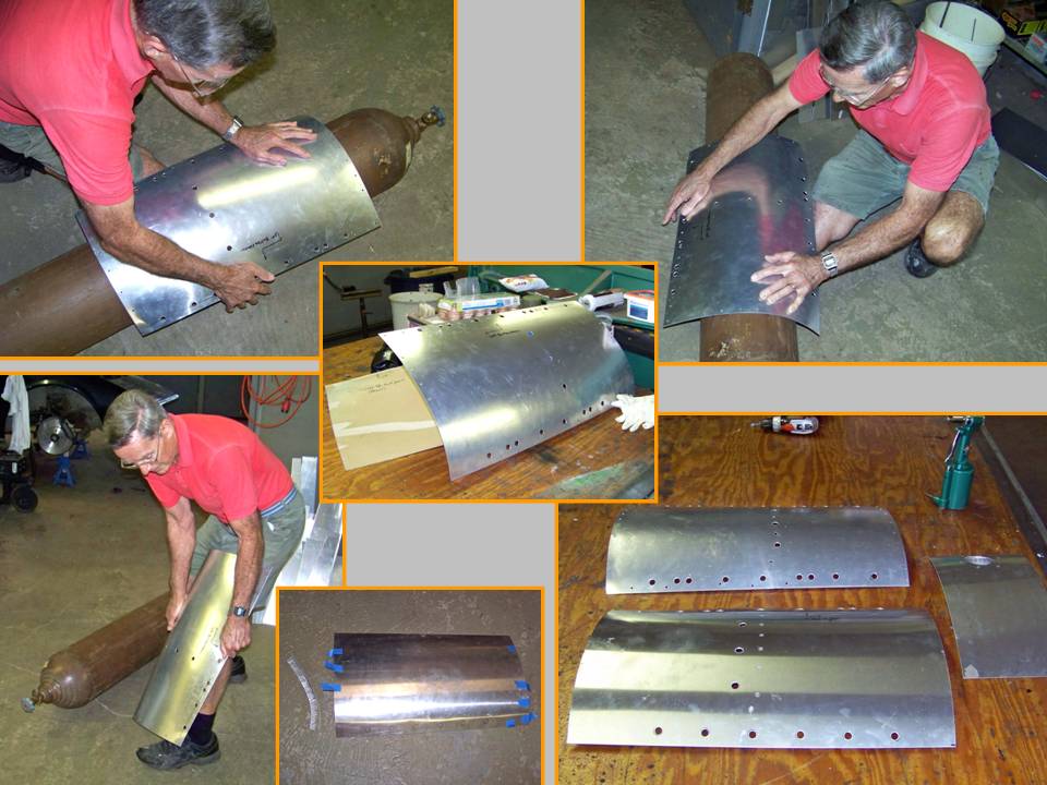 |
Attached panels 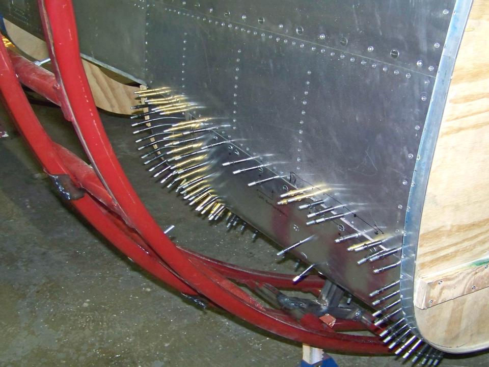 |
Trailer frame work 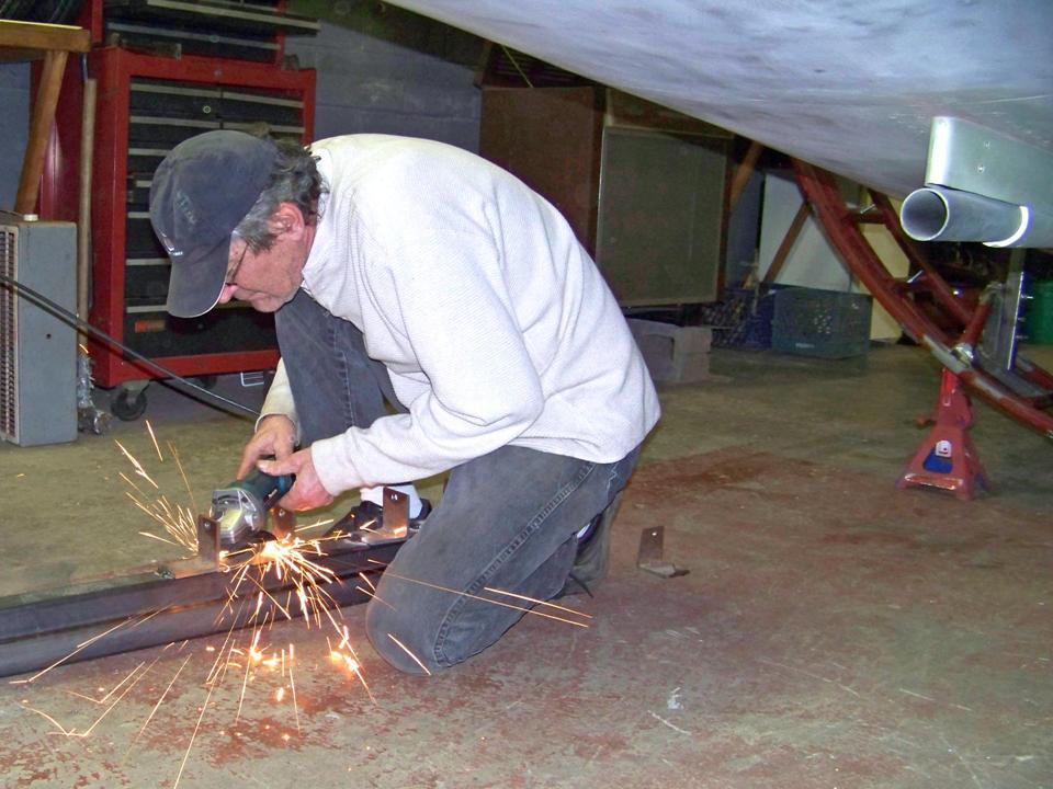 |
The next fuselage component to be built was the 20mm shell casing ejection chute. I originally thought that the small panel aft of the gun bay door contained some heat exchanger vent or a vent that might have had some different venting function. Naturally, I asked Pete Felts about it. Pete is a former Crew Chief whose "hands-on" knowledge of the Hun is top-of-the-line. Here is Pete's response:
Actually, those "vents" are not vents at all. Instead, they are the ejection chutes for the 20mm shell cases. These chutes hook into the back side of the gun breach and when the gun is fired, the chamber rotates and ejects the brass overboard through this chute. The links are fed into a bin that is located just aft of this shell case ejection panel.
My question: Given the small diameter of the shell ejection chute, was there some problem with the thing jamming? Pete's response:
Yep, that was one of the downfalls of the undersized chutes. Pilots were instructed to fire in short bursts, like 10 rounds at a whack. If you held the trigger down for a long burst, it would jam the guns or the casings would eject into the gun bay and blow the door off. I have seen both happen in 'Nam. It's a scary situation either way.
Figure 5, cell 01 shows the basic work required to make the ejection tube and the panel that contained it. Cell 02 shows the completed assembly. Note that I have used pop rivets, so the center of each rivet head shows a small hole. That hole will be filled in later, after which it will be sanded smooth and painted. The result will be a rivet head that looks just like the original.
Note: You can enlarge the pictures by clicking on them. Many of the pictures can be enlarged some more by placing the cursor on them and clicking again. Then maximize the window to get an even closer look.
|
Chute work 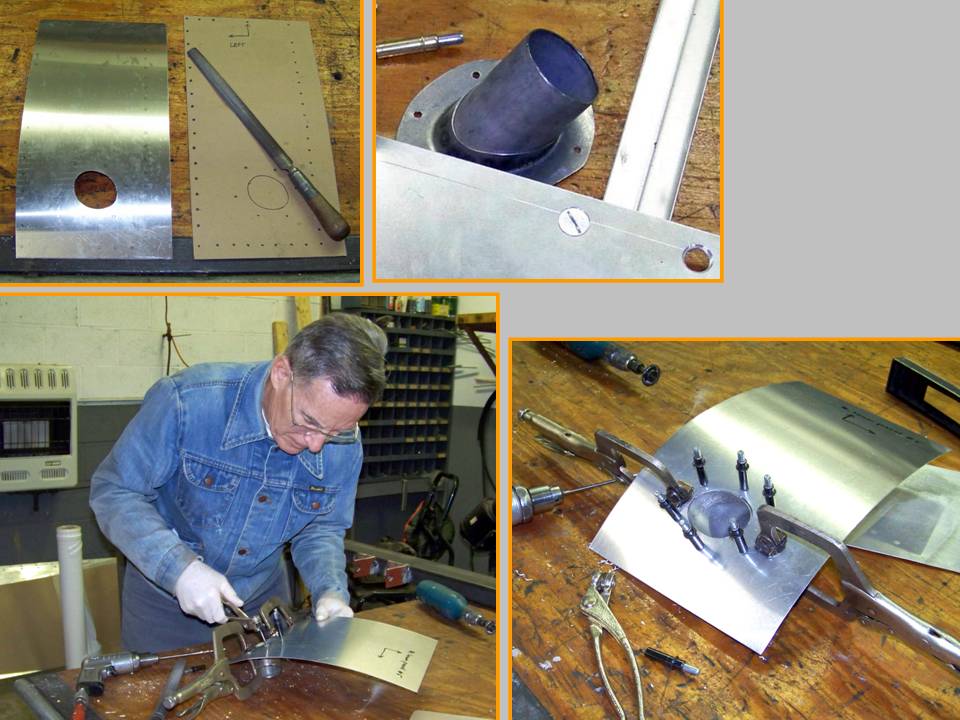 |
Installed chute 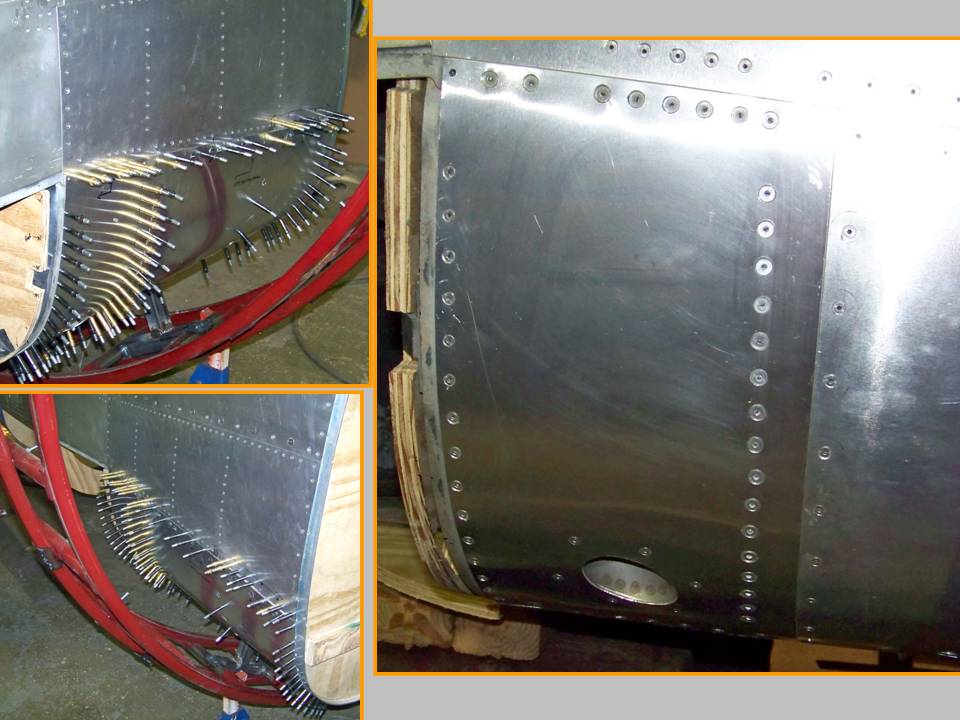 |
Ammo door work 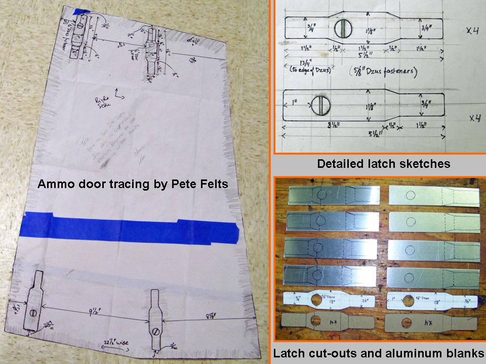 |
Next, it was time to work on the ammo door panel. I had already completed the frame to match the tracing done by Pete Felts. Figure 5, cell 03, shows the tracing and my detailed sketch of the latches, as well as the latch blanks I cut.
Figure 6, cell 01 shows the initial aluminum panel that was cut to fit the tracing and its initial fit on the ammo door frame in the fuselage. As you can tell by looking at the picture, the fit is perfect! At this point, I still have to cut the latch receptacles and I'll have to do a lot of detail work to make the ammo door look "real". Cell 02 shows the F-100D fuselage after more than 2 1/2 years of work. (Yes, both sides are done ...) In the meantime, Steve continued to work on the display trailer. Cell 03 shows Steve after I interrupted him to take the picture.
Note: You can enlarge the pictures by clicking on them. Many of the pictures can be enlarged some more by placing the cursor on them and clicking again. Then maximize the window to get an even closer look.
|
Ammo door cut and fit 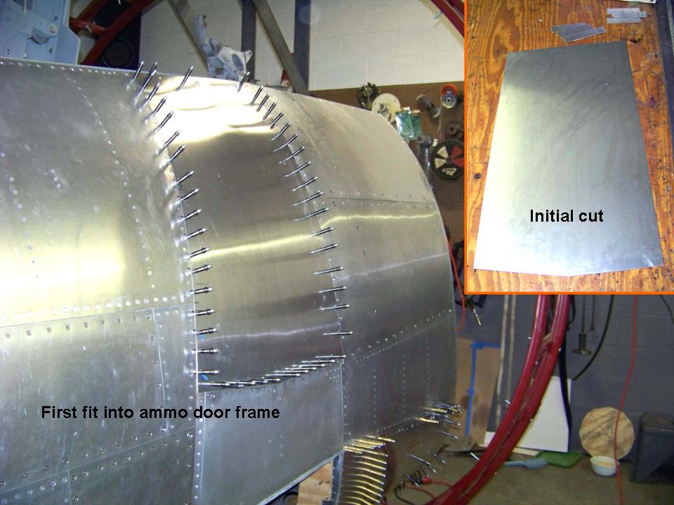 |
Fuselage progress 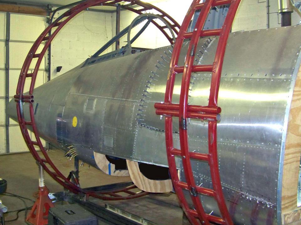 |
Display trailer work 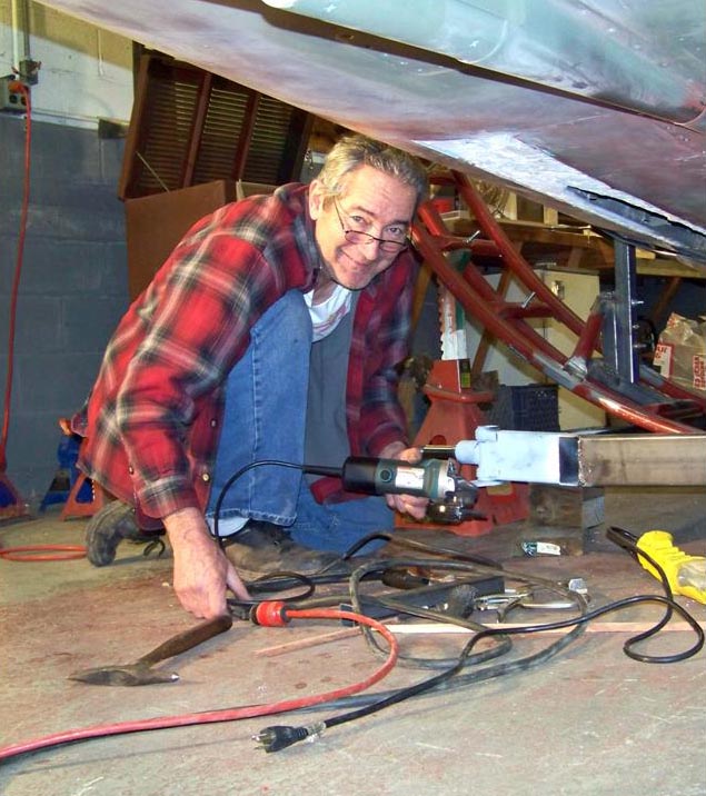 |
As you can tell by looking at Figure 6, cell 02, I finally managed to complete the shell casing ejection chute panels and the panel just behind each of them. (That panel covers the cartridge link bin.) Anyway, I had to drill out a bunch of rivets when I finally bent those two panels around the last bit of bottom frame ... all that bending caused a slight stretch that made each panel overlap by about 1/16" -- so off they came and lots of filing followed. It's a perfect fit now, though! (A mere two months-plus and over 80 hours of work -- never a dull moment!)
The next few weeks will be devoted to making the eight fasteners for the two ammo doors -- it will take a week or two to get them done, but I can at least get them cut out and shaped. Then it's time to punch the holes in the ammo doors to make the back plates for the fasteners. I'll also start on the big gun bay doors ... those will take many months' worth of serious work. Those ammo doors will cover the open section you see in Figure 6, cell 02. (But I sure enjoy doing it, so it's actually inaccurate to call it "work.")
I suspect that some of the F-100 experts wouldn't care much for my frequent use of plywood ... but it sure makes the formers a lot simpler to make and it adds rigidity to the fuselage. Also, since none of the "doors" have anything behind them, none of the latches work and I'm just riveting everything together -- I'll cover the rivets with Bondo and paint where those rivets don't actually belong. The result of using such techniques will look like the real deal, so that's good enough for me ... and this fuselage will really be spectacular in a few years when it has that bright 56-3284 paint job!
As this major "modeling" project moves forward, I will post pictures of the progress we're making. I may not be able to have a real F-100 ... but a properly contructed full-scale model will not be distinguishable from the real thing. Stay tuned.
While the rebuilding and restoring efforts are important, please remember that the main focus of the F-100 project is its database. If you can supply stories and pictures that reflect your experience with the Hun, please do so. (You can click on the Contact me link to send me an email.) The objective is to develop a very comprehensive personal history of the Hun and of the people who flew and maintained her. You and the Hun deserve to be remembered in your own words.
If you want to return to the home page, you can either click on the
Home link shown here or by clicking on the Home link shown on left side of your screen. (You can also use any of the navigation bar links shown on the bottom of the screen to move around this website.)