|
Cut panels 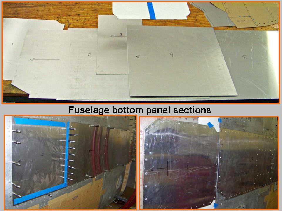 |
Gun bay door templates 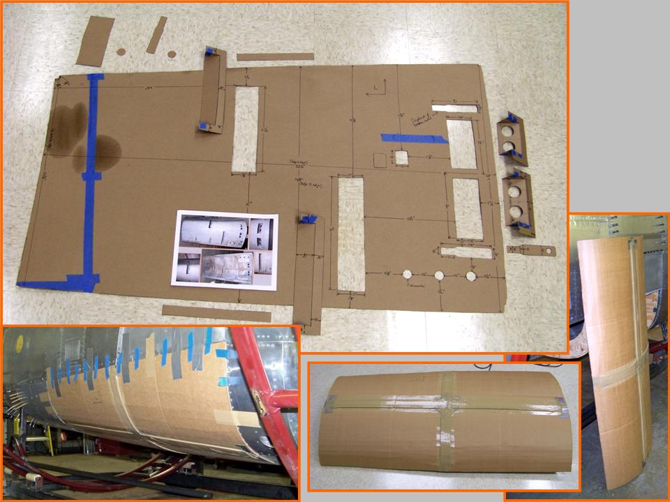 |
Gun bay door work  |
The Fuselage, Part 6 page showed major progress on the first 23+ feet of the fuselage. You also saw that the roll cage performed its intended job perfectly as we rolled the fuselage on its side to make work on the bottom sections easier. You also saw major progress on the spine section.
On this page, I'll start documenting the work done on the fuselage bottom sections, including the manufacture of the gun bay doors and the final installation of the gun blast panels. (Given the size, the complex curves along the top, bottom, and diagonal, plus the many vents that have to be fit into the gun bay door's surface, I suspect that this portion of the building project will keep us busy for a long time ...) Naturally, there will also be some updates to show the continued progress on the spine section as I move it to the fuselage frame aft of the canopy.
The center bottom panels, including the nose gear doors, were the easiest to make. As always, I started with paper tracings from an actual F-100D, then cut the cardboard templates to check the fit on the frame. When the carboard templates fit properly, they were traced on 0.060 aluminum sheet, which was then cut for final fitting.
Cell 01 in Figure 1 shows a few of the freshly-cut aluminum fuselage bottom panels and their installation on the frame. As you can tell, I have not yet done any of the detailing work on the nose gear doors.
Figure 1, cell 02 shows the gun bay door template. (Thanks again to Dean Demmery at the Carolinas Aviation Museum for letting me have some "quality time" with his F-100D.) Note the photo stack deposited on the template -- this photo stack provides the gun bay door details for the finishing work. You can also see the heavy gun bay door cardboard model taped to the frame. Finally, the composite picture in cell 02 shows the cardboard model in "stand-alone" mode, stiffened with tape.
Figure 1, cell 03 shows condiderable progress on the gun bay door. The aluminum sheet has been cut and I'm making the initial bends around a smooth-barked tree. After many hours of bending and pounding -- with a rubber hammer -- the gun bay door panel fit the frame, but it would not hold its shape when we took it down for additional work. I suggested to Steve that we might put some temporary outside stiffeners on the panel while the panel was still on the frame, so that the shape could be retained for additional work. The additional work included putting in the internal stiffeners and cutting all the holes for the vents and fasteners. (The picture shows Steve putting clecos in to hold the internal stiffeners, while the external stiffeners do their critical job of maintaining the gun bay door shape and curvature.)
Note: You can enlarge the pictures by clicking on them. Many of the pictures can be enlarged some more by placing the cursor on them and clicking again. Then maximize the window to get an even closer look.
|
Cut panels |
Gun bay door templates |
Gun bay door work |
The basic gun bay door shape you see in Figure 1, cell 03, turned out to be the culmination of quite a few experimental procedures. While the template was a perfect two-dimensional copy of the real gun bay door, transforming that cardboard model into a perfect gun bay door turned out to be a major challenge.
Given the size of the gun bay door frame, tracing the cardboard template on a piece of aluminum sheet and then cutting and shaping the aluminum panel did not work well. We finally managed to get a good gun bay door panel "print" on the aluminum by painting the gun bay door opening's outside edges with a Prussian Blue mix and then tacking on an oversized 0.060 aluminum sheet against those edges with the help of clecos. The result was a perfect print that made the "first cut" fit perfectly. Much work remains to be done ... for one thing, there are many vents in those gun bay doors. But the gun door shape is perfect at this point.
Figure 2, cell 01, shows that the gun bay door fit the fuselage frame perfectly. At this point, the external stiffeners are still doing their job of holding the gun bay door shape. Cell 02 shows the top gun bay door without the external stiffeners ... at this point, the internal stiffeners maintain the gun bay door shape. (You can also see that the installation of all the fuselage bottom panels has been completed.) The bottom gun bay door still has to go through the external-to-internal stiffener stages ... Cell 03 shows me doing a lot of cutting work with various instruments -- those openings are critical to making the "model" gun bay door look like the real thing.
Note: You can enlarge the pictures by clicking on them. Many of the pictures can be enlarged some more by placing the cursor on them and clicking again. Then maximize the window to get an even closer look.
|
External stiffeners  |
Fuselage bottom view  |
Gun bay doors  |
Once the gun bay doors were put in their frames, the four fasteners -- two per door -- and the small rectangular access panels -- one per door -- were traced, cut, and shaped. Next, I cut the holes for the Dzus fasteners. I also cut the backing plates for these components, remembering to drill some over-sized holes in the fastener backing plates so that the Dzus backs would fit through them, thus letting each Dzus head fit flush against the fastener surface. The the next job was to cut the basic vent shapes and to form the vents. Figure 3, cell 01 shows the "manufacture" of some of the vents. Cell 02 shows some of steps required to install the vents. Cell 03 shows the completed gun bay doors, primed with self-etching lacquer.
Note: You can enlarge the pictures by clicking on them. Many of the pictures can be enlarged some more by placing the cursor on them and clicking again. Then maximize the window to get an even closer look.
|
Vent shaping  |
Fuselage bottom view 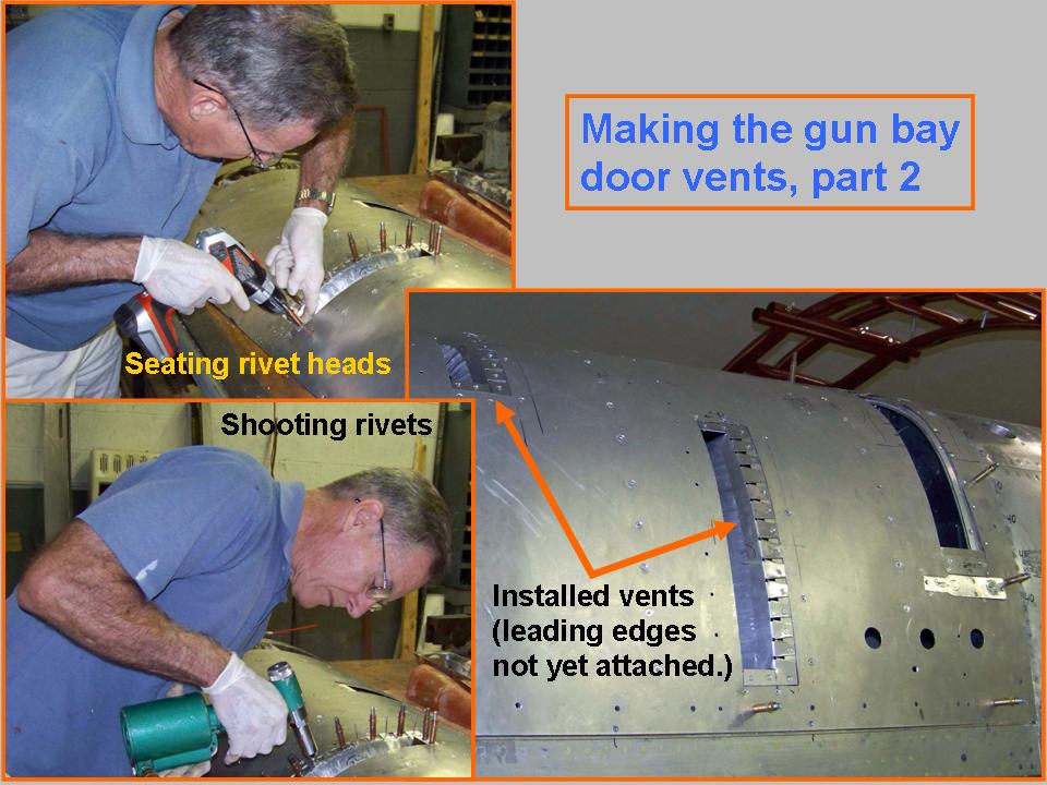 |
Primed gun bay doors  |
While the gun bay door construction continued, I worked on the small nav light panel just in front of the nose gear door. I had the panel tracing and some very detailed photos, plus a light receptacle that originally served on a (civilian) Sabreliner.
As I started cutting the metal, I was surprised that a supersonic aircraft would have such a "draggy" nav light construction -- 1/8" aluminum base, roundhead Phillips screws instead of counter-sunk flat-head screws, and so on. As usual, Pete Felts put that bit of concern in perspective -- by pointing out that a normal load on the wing stuck a LOT of "stuff" into the breeze, like huge fuel tanks and a wide variety of weapons. Anyway, I made sure that the "home-built" nav light panel matched the original in all details. Figure 4, cell 01 documents the "manufacturing" process. The only thing missing at this point is the nav light glass lens ... I'll have to either make one of plastic or find a Sabreliner lens that fits. (Like almost all of the F-100 components, making this small piece turned out to be a lot more challenging than it first appeared to be ... you're looking at just over 20 hours of work spread over a month.)
Figure 4, cell 02 shows the completed fuselage front bottom section. Note the installed gun bay doors, the gun blast panels, and the installed guns. The final coat of the proper aluminum paint has been applied, so this section of the fuselage shows major progress. (You can see how the gun blast panels were made by selecting the "Gun blast panels" option from the Restoration Menu.)
Cell 03 show the front fuselage segment free off the roll cage. Note the steel stubs that anchor the fuselage to the trailer frame. We are now ready for the final touch-up work on this fuselage segment. The next part of the project involves the fuselage segment aft of this one ... that work will be documented on the Fuselage (Part 8) page option. (Check the restoration menu.)
Note: You can enlarge the pictures by clicking on them. Many of the pictures can be enlarged some more by placing the cursor on them and clicking again. Then maximize the window to get an even closer look.
|
Nav light panel 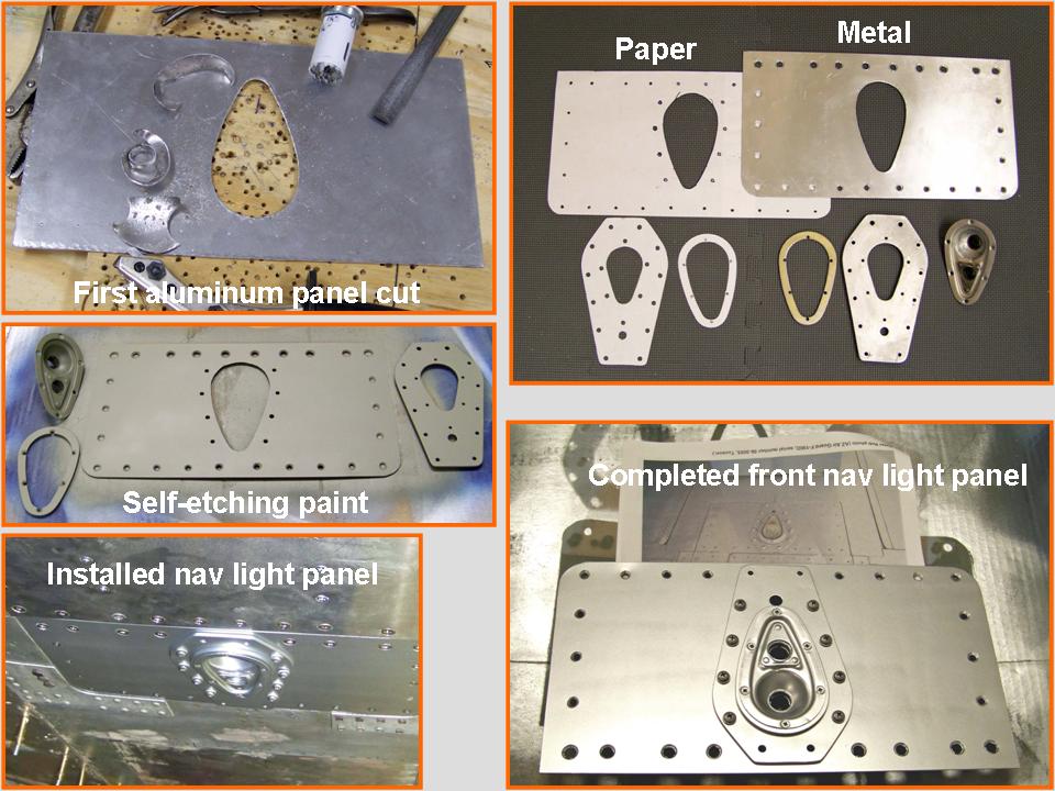 |
Completed panels  |
No more roll cage 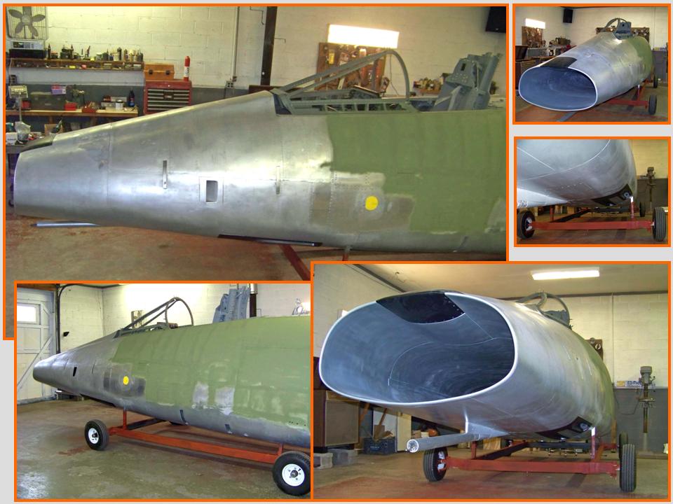 |
As this major "modeling" project moves forward, I will post pictures of the progress we're making. I may not be able to have a real F-100 ... but a properly contructed full-scale model will look like the real thing. Stay tuned.
While the rebuilding and restoring efforts are important, please remember that the main focus of the F-100 project is its database. If you can supply stories and pictures that reflect your experience with the Hun, please do so. (You can click on the Contact me link to send me an email.) The objective is to develop a very comprehensive personal history of the Hun and of the people who flew and maintained her. You and the Hun deserve to be remembered in your own words.
If you want to return to the home page, you can either click on the
Home link shown here or by clicking on the Home link shown on left side of your screen. (You can also use any of the navigation bar links shown on the bottom of the screen to move around this website.)