|
First cuts 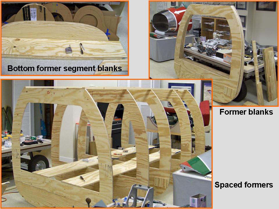 |
Basic Skeleton 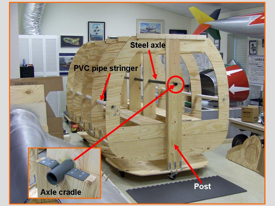 |
Dive brake work  |
The Fuselage (Part 7) page documented the work done on the fuselage section that contained the cockpit tub. On this page, I'll document the "manufacture" of the 97-inch fuselage section just aft of the canopy. I'll also show the completion of the windscreen and the canopy and I'll show the attachment of this new fuselage section to the 23-foot fuselage section that was shown on the Fuselage (page 7) page. Finally, you will see the completed paint job on the combined fuselage sections.
The first job was to make the fuselage "skeleton" to which the aluminum skin plates were to be attached. That "skeleton" consisted of the fuselage "formers" that produced the correct cross sections and the "stringers" that maintained the spacing between the formers to ensure that the correct longitudinal shape would be maintained. As you can tell by looking at Figure 1, cell 01, shows the production of the plywood formers. Cell 02 shows the initial PVC-pipe interior stringers ... and a steel pipe that would become the "axle" around which the fuselage segment could be rotated. (Being able to rotate the fuselage would make it easier to work on the fuselage bottom and top sections. Because this fuselage section was much lighter than the section containing the fuselage tub, we did not need to use the more elaborate roll cage you saw in the Fuselage (Part 7) segment. The composite picture in cell 03 shows the manufacture of the dive brake and its center post. The dive brake would be the first bottom section on this new fuselage segment. (You can examine the manufacture of the spine section by taking a look at the Fuselage (Part 6) page ...)
Note: You can enlarge the pictures by clicking on them. Many of the pictures can be enlarged some more by placing the cursor on them and clicking again. Then maximize the window to get an even closer look.
|
First cuts |
Basic Skeleton |
Dive brake work |
As you can tell by looking at Figure 1, cell 03, the manufacturing process remains the same ... the paper tracings of the real airplane components are copied to thin cardboard, the fit is checked carefully, and the cardboard then becomes the template for the aluminum piece.
A note by Bob Dunham:
About your use of the �dive brake� label, I'll be a nit - call it a "speed
brake". In fact, that's what the -1 says; all of us used the term, and it's
printed on the throttle switch (the one on top that lowers and raises the
"speed brake". I think "dive brake" went out of use in WWII.
The cutout on the speed brake enables us to carry a centerline store - originally for a nuke, but probably more often was a SUU dispenser for carrying practice bombs. The SUU-21 (? I think) had doors that you had to open that replicated "arming" the nuke. I remember the low level rule was to not bring grass back in your SUU.
The next major step in the F-100D fuselage manufacture was to transport the new aft-of-cockpit section from my F-100 "museum" where I had constructed it to Steve's place. After that task was completed, we could begin attaching the 1/8-inch thick, 2-inch wide aluminum strips to the plywood frame. The new skin plates could then be attached to these aluminim strips. In the meantime, the canopy had to be completed and attached to the cockpit section. (Without the canopy in place -- and in the closed position -- I did not know the precise curvature and placement of the spine panel directly aft of the canopy.)
We decided to wait until the canopy was in place before attaching the new fuselage section to the now-completed front fuselage section. (You can check the Fuselage (Part 7) web page to see the completion of that front section.) In the meantime, we could start putting the aluminum components on the bottom of the new aft-of-cockpit section. I had already completed much of the dive brake section, so that would be a logical place to start.
The composite picture in Figure 2, cell 01, shows us loading the new fuselage section on Steve's trailer. Cell 02 shows the new section in Steve's workshop. If you take a good look at the composite picture shown in cell 02, you can see that we have made some progress on the windscreen ... all the frame strips are done and the only remaining work will be the installation of the windscreen glass. (We need to find a good way to get new plastic pieces to fit the frame. We're hoping that this job can be farmed out -- molding thick plastic into the proper shape without causing distortions is likely to be well beyond our skill set. If you know somebody who might be able to get this job done without demolishing my strained piggy bank, please let me know!) Cell 03 shows the work done on the strip of inspection panels. Note the photo that shows the strip of inspection panels along the left side of the fuselage.
Note: You can enlarge the pictures by clicking on them. Many of the pictures can be enlarged some more by placing the cursor on them and clicking again. Then maximize the window to get an even closer look.
|
Transport 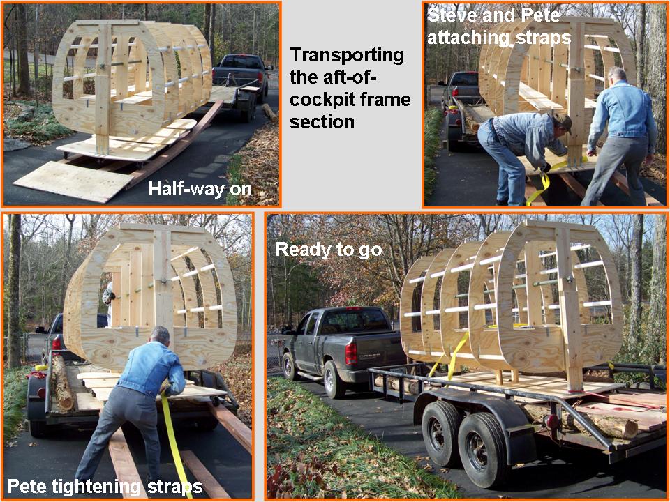 |
In Steve's shop 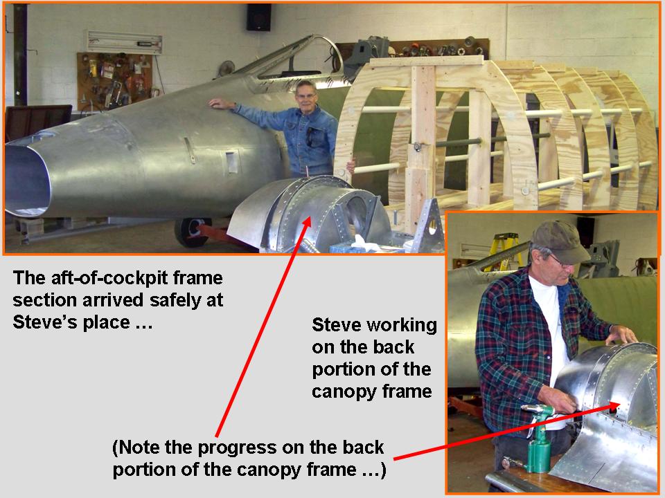 |
Panel strip 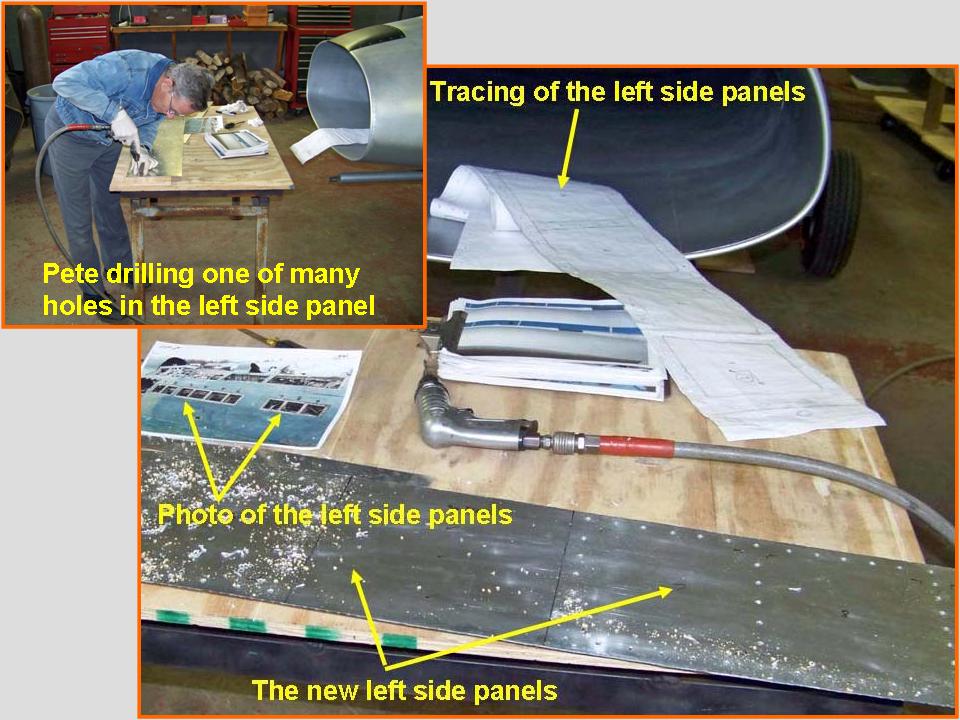 |
The length of the side panel you saw in Figure 2, cell 03, became the perfect measure for determining the precise length of the plywood frame. I modified the first bulkhead to slide along the center and side stiffeners, thus enabling me to slide the bulkhead back and forth to match the panel length exactly. While that little job was being completed, work on the windscreen and canopy frames continued. Figure 3, cell 01, documents the progress on the almost-completed frames. Now I'm trying to find somebody who knows how to blow thick plastic to form the windscreen side panels and the canopy. In the meantime, I'll pretend that the missing "glass" is actually very, VERY clean ... that sure is a cheap solution in the short run. (Bob Dunham has a story about very clean canopy glass -- check out his contributions in the database portion of this project.)
After the fuselage frame was finally completed, it was time to hang the speed brake in its proper place. The composite picture in Figure 3, cell 02, shows the speed brake attached ... with clecos at this point. The picture also shows the two panels that will be tackled next. Incidentally, the nav light in the 1/48-scale model is supposed to be red ... I had not yet painted it. I found a perfect (vintage) red truck cab light that was exactly the right size and shape to fit the nav light panel. (The next search routine would have led me to look for old Sabreliner lights -- the old Sabreliner has a LOT of parts that fit an F-100 very nicely ...) Anyway, the composite picture in Figure 3, cell 03, shows the work done on the nav panel light. The work is not quite done yet ... for one thing, the clecos will have to be replaced by the appropriate rivets and screws.
Note: You can enlarge the pictures by clicking on them. Many of the pictures can be enlarged some more by placing the cursor on them and clicking again. Then maximize the window to get an even closer look.
|
Canopy frame 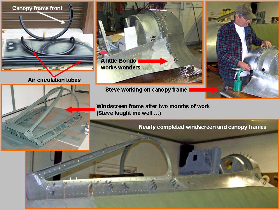 |
Speed brake 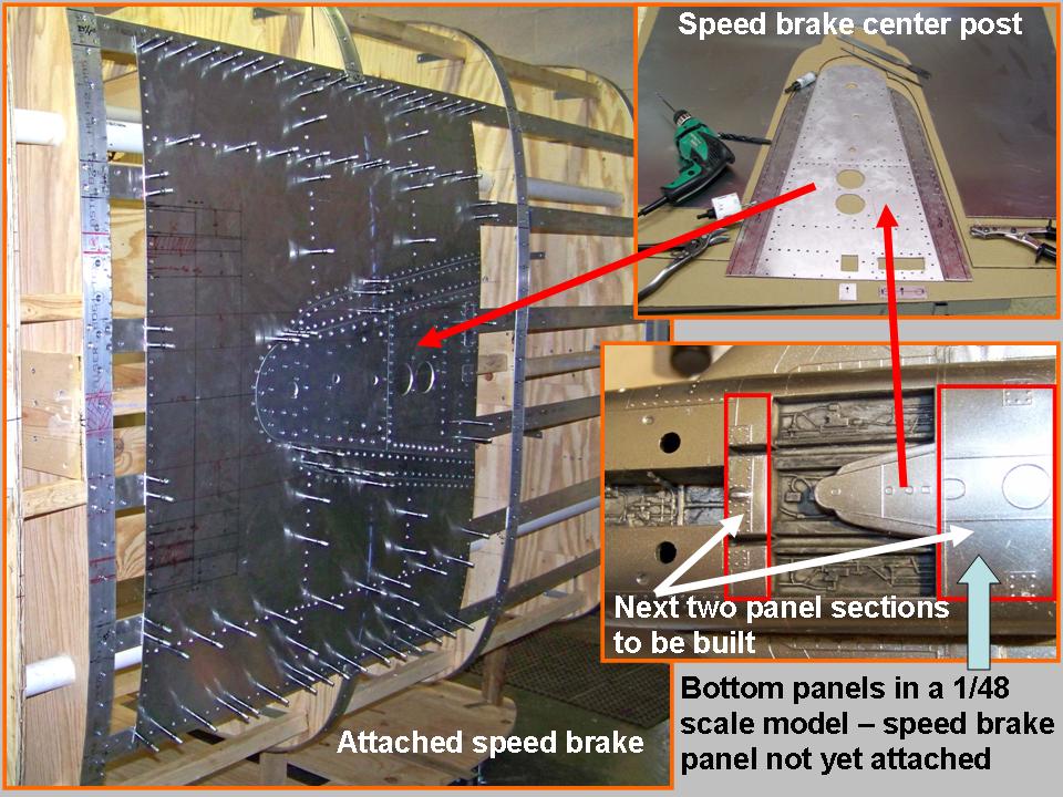 |
Nav light panel 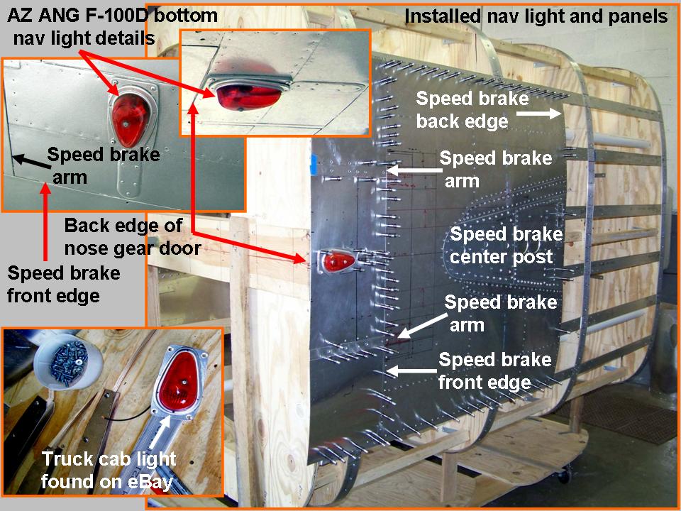 |
After installing the speed brake and the panels just in front of it, the time had come for a serious look at the many remaining bottom panel tracings. To make sure that I would know which panel went where, I made an "overview" sketch as I was making the tracings. To help preserve the documentation, I made a Powerpoint slide, then saved that slide as a .jpg file for use on this website. You see the results of that effort in Figure 4, cell 01.
As usual, Pete Felts became the "go to" guy when I wanted to know what the
various access panels were for. Here is Pete's response to one of my emails:
The two 6x6 access panels cover the fuselage tank probes, the round one is
for the fuselage boost pump, the U-shaped one is for the cannon plug when
we had a nuke on the centerline. I don't remember what the two larger
round holes were for. I do know that those holes had nothing to do with
fuel, since we didn't carry fuel on the centerline. I'll have to do some
more research.
Next, it was time to transfer the fuselage center bottom panel tracings to cardboard to check the fit. When the fit was judged to be "just right", the cardboard templates were transferred to aluminum, cut, and shaped. (If you're spotting a familiar process, you're right ... that's how all of the aircraft components were made.)
After the center panels were checked for their final fit, the seemingly endless drilling began to make the various fastener holes for the rivets and screws. (There are a LOT of rivets in these fuselage bottom pieces!) Each hole had to be de-burred to produce a clean fit against the stringers. After the panels were properly de-burred, they were attached (again ...) with clecos. Finally, each hole had to be counter-sunk to ensure that the fasteners would be level with the panel surfaces. Finally, the riveting began to attach the panels permanently. You see the partially completed results in Figure 4, cell 02. The nearly completed bottom panel section is shown in Figure 4, cell 03.
Note: You can enlarge the pictures by clicking on them. Many of the pictures can be enlarged some more by placing the cursor on them and clicking again. Then maximize the window to get an even closer look.
|
Panel drawing 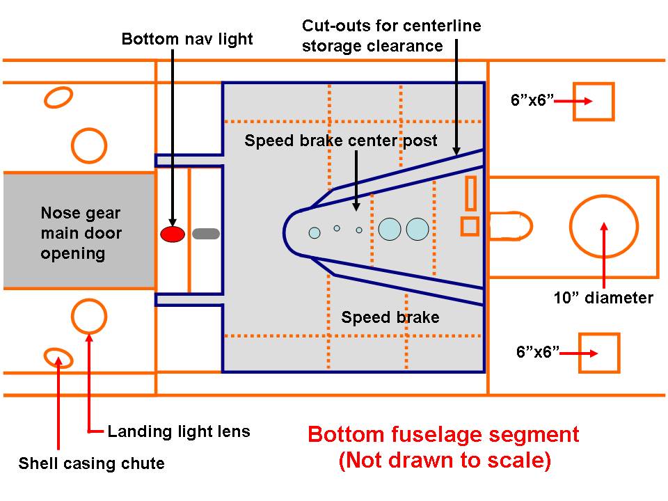 |
Bottom panels 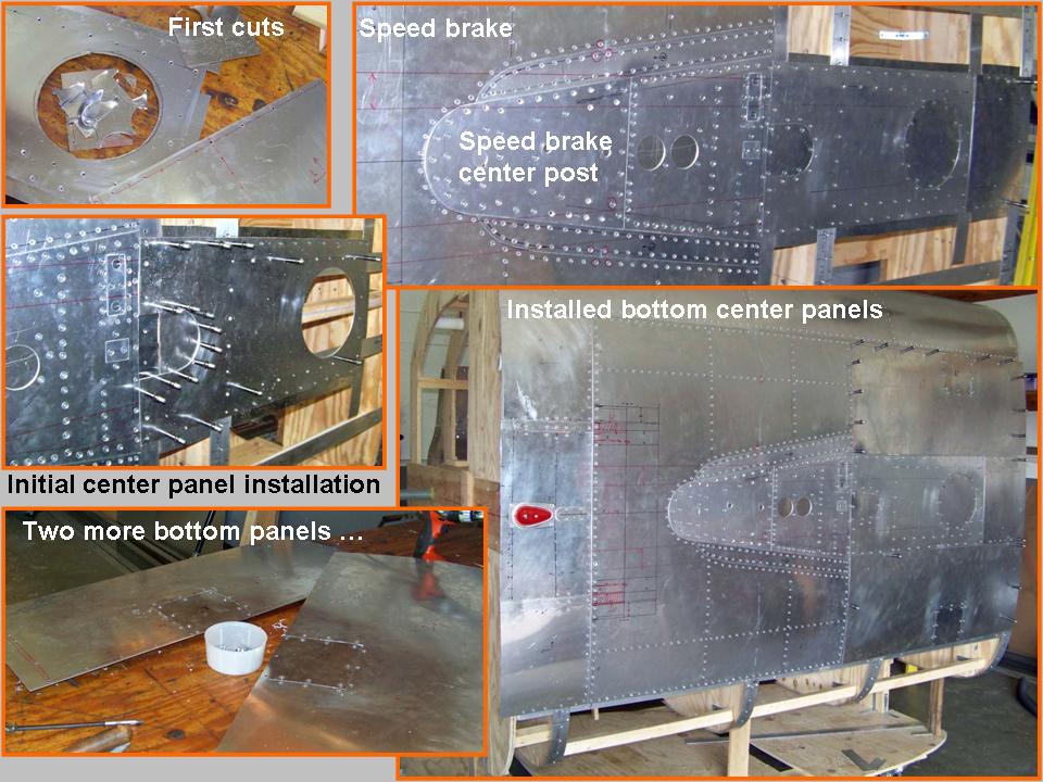 |
Almost done ... 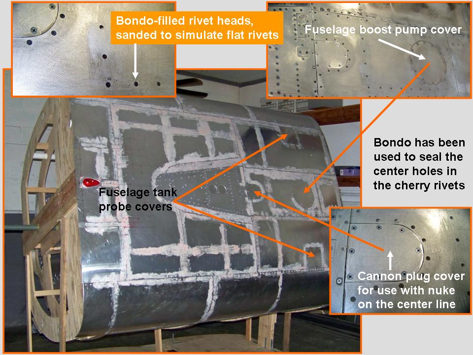 |
When the new bottom section skin panels were all in place and properly prepared, it was time to spray the panel lines with self-etching lacquer and to perform a final check to see if the Bondo work had yielded the desired results. In the meantime, we had installed four steel support stubs. These stubs will later be used to anchor this fuselage segment to the trailer extension. In turn, that trailer extension will be attached to the main trailer ... proper alignment will ensure that this fuselage segment will fit the fuselage section in front of it.
Next, two coats of the self-etching primer were applied to the entire
surface, followed by more sanding. When the surface looked nice and
smooth, I applied two coats of aluminum lacquer, followed by a finishing
coat of "brilliant alluminum" lacquer. Finally, we rolled the fuselage
segment level in preparation for its attachment to the trailer extension.
Figure 5, cell 01, shows a composite picture that illustrates the process.
(Comment by Pete Felts after I emailed him a copy of this picture:
Note: You can enlarge the pictures by clicking on them. Many of the pictures can be enlarged some more by placing the cursor on them and clicking again. Then maximize the window to get an even closer look.
|
Completed bottom 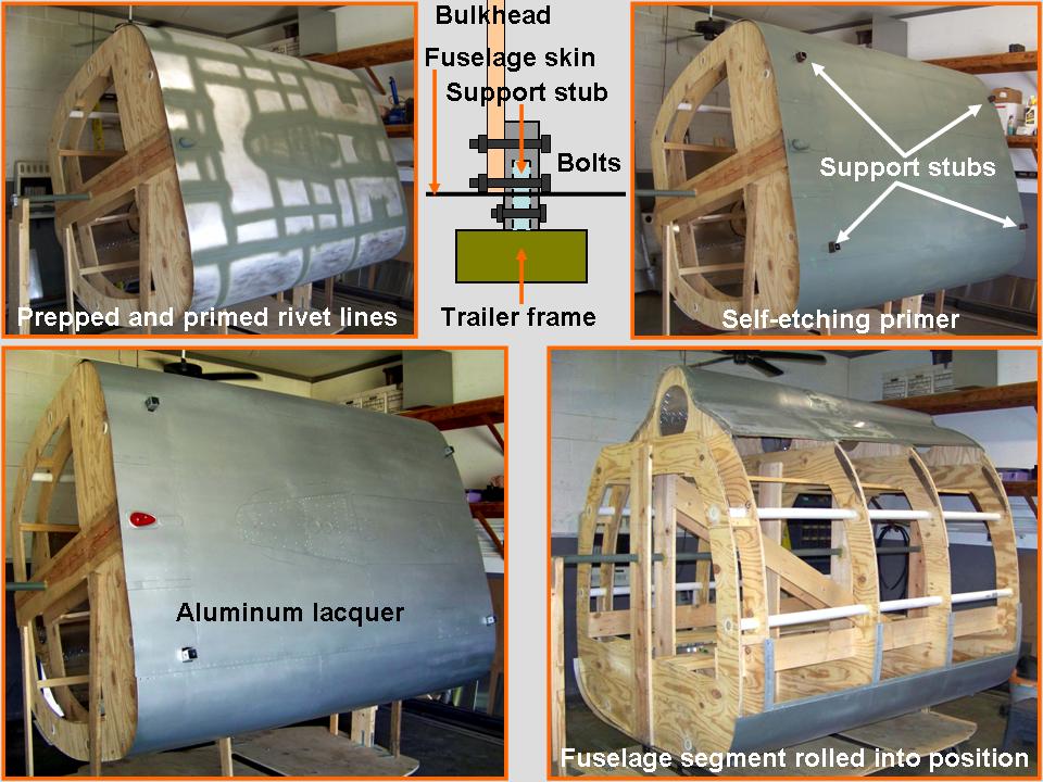 |
On the frame 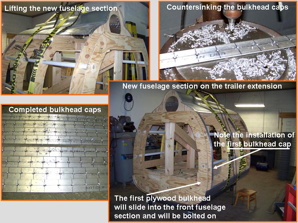 |
Bolted on ... 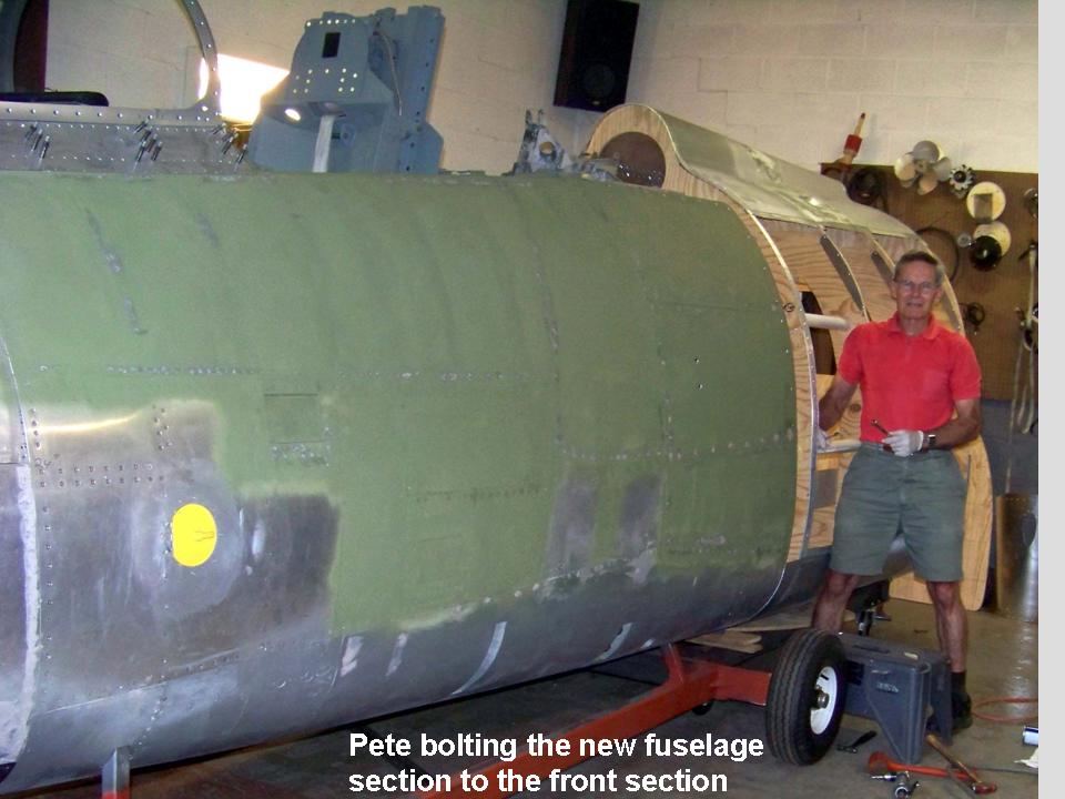 |
The pictures you see in Figure 5, cells 02 and 03, document the installation of the new fuselage section on the trailer extension and the attachment of the new fuselage section to the section in front of it. Cell 02 also shows the "manufacture" of the bulkhead caps that will serve to anchor the stringers and skin panels later. At this point, the new fuselage segment has been clamped in place on the trailer extension. The next step will be to finish bolting the support stubs to the bulkheads and then to weld those stubs to the trailer extension. The new trailer extension will also be welded to the main trailer. (You will see that part of the building process in Fuselage, Part 9.)
As this major "modeling" project moves forward, I will post pictures of the progress we're making. I may not be able to have a real F-100 ... but a properly contructed full-scale model will not be distinguishable from the real thing. Stay tuned.
While the rebuilding and restoring efforts are important, please remember that the main focus of the F-100 project is its database. If you can supply stories and pictures that reflect your experience with the Hun, please do so. (You can click on the Contact me link to send me an email.) The objective is to develop a very comprehensive personal history of the Hun and of the people who flew and maintained her. You and the Hun deserve to be remembered in your own words.
If you want to return to the home page, you can either click on the
Home link shown here or by clicking on the Home link shown on left side of your screen. (You can also use any of the navigation bar links shown on the bottom of the screen to move around this website.)