|
Welding action ... 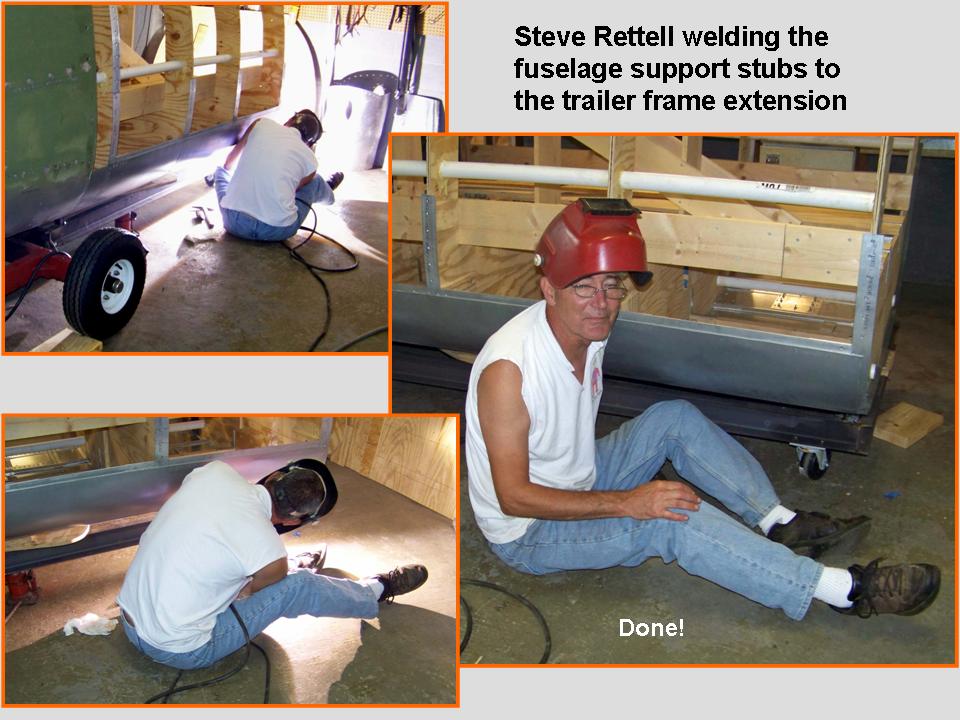 |
Side panel installation  |
Two forward, one back 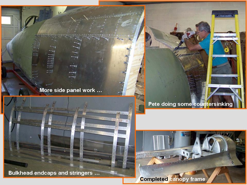 |
The Fuselage (Part 8) page documented the work done on the fuselage section just in back of the canopy and its attachment to the fuselage section in front of it. On this page, I'll document how the bulkhead caps and stringers were attached to the new section and how the new fuselage panels for that section were made and attached. You will also see the completion of the crush panel and the canopy frame. Finally, you will see the application of the self-etching primer and the application of the aluminum lacquer to the combined fuselage sections.
Figure 1, Cell 01, shows Steve Rettell welding the new fuselage support stubs to the trailer extension. (At this point, I had already drilled the 3/8" holes through the bulkheads and the steel stubs and bolted the stubs to the bulkheads. Steve also welded the trailer extension to the main trailer, so the new fuselage segment is very firmly attached.)
Figure 1, cell 02, shows a composite picture that documents the first side panel installation on the fuselage aft-of-cockpit section. Cell 03 documents the nearly-completed metal work on the fuselage aft of the cockpit section ... just before I discovered a major discrepancy. As it turned out, this was a perfect example of two steps forward, one step back.
Note: You can enlarge the pictures by clicking on them. Many of the pictures can be enlarged some more by placing the cursor on them and clicking again. Then maximize the window to get an even closer look.
|
Welding action ... |
Side panel installation |
Two forward, one back |
After the metal work you see in Figure 1, cell 03, had been done ... I discovered that the crush panel front edge was almost 1.5 inches below the back of the canopy frame. (The canopy frame's back edge fits over the front of the crush panel.) Well, I suppose that's the kind of thing that is likely to happen when you're working with two-dimensional tracings and pictures to produce a three-dimensional object in multiple sections ... In any case, it illustrates the engineering philosophy that you have to use your head to save your backside. (OK, yes, I've cleaned that up a little ...)
The initial reaction was to think about lowering the back of the fuselage section aft of the cockpit, thus raising the front of the spine section. The problem with that notion was that it would change the slope of the spine section -- so that was not a good solution. The problem stayed with me through the day, the evening, and the night.
Finally, at about 1:42 a. m., it occurred to me that I had built the spine section on a movable frame that was bolted to the main bulkhead section. Therefore, we could raise the entire spine section without altering its slope. The problem with that solution was that we would have to take all the skin panels down, as well as the frame. (The lower left insert in Figure 1, cell 03, shows the frame end caps and stringers we took down after the skin panels had been removed.) After Steve and I had spent two days taking the results of our hard work apart, we moved the spine section and, yes, the fit and slope were now perfect.
Unfortunately, the just-described solution led to yet another problem ... we would have to fit the crush panel sides to match the pitch on the canopy frame AND the section that fit against the back of the crush panel. The solution to THAT problem was to take the spine section apart and then to reshape the entire spine section frame. I sure wish I had not tried to save time by building the entire aft-of-cockpit section separately ... but that's the advantage of 20/20 hindsight. Never mind, with that valuable hindsight, we spent the last week of August and the first two weeks of September, 2010, re-doing a lot of work. The good news is that the "model" will match the real F-100D fuselage when we're done.
The results of all the revisions are documented in Figure 2. The composite picture in cell 01 shows the crush panel that I re-cut and re-shaped and the installation of the crush panel end cap. It also shows Steve working with the (removed) back canopy panel to make the small adjustments that would ensure that the new crush panel would fit well. Note also the temporarily-attached side panels that were used to check the fit on the repositioned end cap and stringer section.
Figure 2, cell 02, shows a composite picture that documents the re-attached end cap and stringer framework and the re-attachment of the new crush panel.
While we were doing all the re-work, I also wanted to start the work on the inspection plates that were located on the large skin panels. Figure 2, cell 03 shows a collection of pictures that served to ensure that the inspection panel sizes and placement would be accurate. (I took the picture in the upper-left corner at Tom Reilley's place in Kissimmee, Florida on 20 March, 2005. Pete Felts took the picture in the upper right- hand corner -- that picture shows the inspection panel on 56-3000. "Smitty" Smith made it possible for me to get inside the Arizona Air Guard fence at Tucson, AZ, to let me take the pictures of 56-3055 and its right-side inspection panels on 5 February, 2007. That large rectangular panel you see in the center-bottom picture is apparently not found in the earlier models, because I did not see it in any of late-1950s F-100D pictures I examined.)
Special word of thanks: Pete Felts, who has taken so many of the detailed pictures of 56-3000 -- not to mention all those skin tracings that helped me make so many of the canopy frame components and inspection plates -- wrote the following comment: "I think it would be appropriate to show appreciation to Chief MSgt. Anthony Jackson of the 149TFG, Texas ANG. 56-3000 provided many etchings and "detail" pictures and Tony was very kind to grant me free access to the airplane."
I certainly concur with Pete Felts' comments and I add my heart-felt "Thanks!" to Tony.Note: You can enlarge the pictures by clicking on them. Many of the pictures can be enlarged some more by placing the cursor on them and clicking again. Then maximize the window to get an even closer look.
|
Crush panel work ... 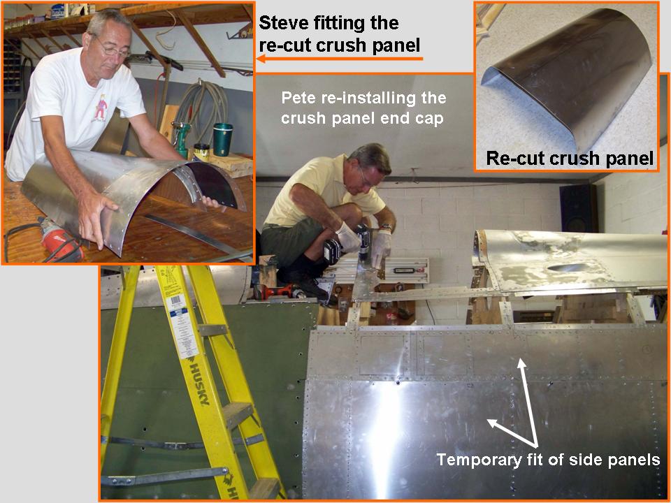 |
Re-installation work 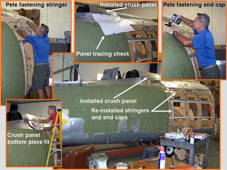 |
Inspection panels 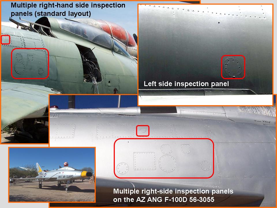 |
Figure 3, cell 01, shows a composite picture that documents the work on the inspection panels you saw in Figure 2, cell 03. This picture shows Steve cutting the holes for the multiple right side inpection panels. While Steve was working on the inspection panels, I traced, cut, and installed the panels on each side of the crush panel. Figure 3, cell 02, illustrates the work done on these panels. Note also that the left side main side panels have been attached. Cell 03 shows the completed metal work on the fuselage segment's right side. Note that the inspection plates have all been installed over their back plates. At this point, the Bondo work has been started to fill the holes in the pop rivet centers and to fill in minor metal flaws. (Look just in front of the inspection panel section. When the Bondo has been sanded down and painted, the pop rivets will look just like the "real" rivets that were used on the F-100.)
Note: You can enlarge the pictures by clicking on them. Many of the pictures can be enlarged some more by placing the cursor on them and clicking again. Then maximize the window to get an even closer look.
|
Inspection panels 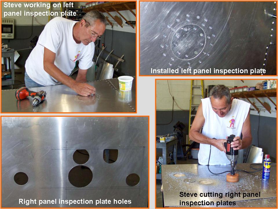 |
Re-installation work 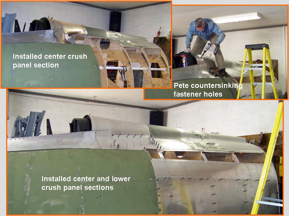 |
Completed metal work 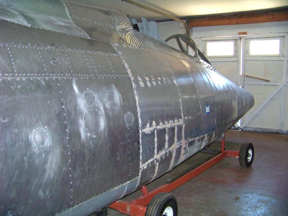 |
We completed all the metal work on the fuselage segment on Thursday, 28 October, 2010. The next step will be to start prepping the fuselage for sanding, a process that will take several months. (A good paint job begins with a thorough preparation of the surface that will be painted.) Figure 4, cell 01, shows the completed metal work on the fuselage segment, ready for sanding. We have rolled the fuselage segment outside to let us blow the Bondo- and aluminum dust away with the help of a B-I-G fan and the wind that tends to be ever-present during the fall season. Note the inset that shows the paint job that will be applied to this fuselage segment. The 1/72-scale model reflects a 48th TFW Hun (as flown by Col. Smith) during the 1960 William Tell Gun Meet. I was very fortunate to have an official USAF photo of this aircraft -- and an old Hasegawa kit's painting instruction sheet that matches the photo perfectly.
Because sanding is an "outside job" and the weather doesn't always cooperate, I managed to coninue work on the canopy's "back deck" components. (I had been working on these pieces for well over a year, "in-between" the work done on the fuselage.) Figure 4, cell 02 shows the results of a lot of close-up picture-taking, measuring, model-making, metal cutting, and assembly. At this point, some small parts have yet to be installed and the rivets and bolts still have to be painted black to match the assembly. Having a really detailed tech manual drawing was really helpful. (Incidentally, the plate in front of the box assembly on the left side -- your right side as you look at the picture -- is not shown in the tech manual drawing, but it does show up in the pictures I took, so I added it ... one of the easier pieces to manufacture!) Figure 4, cell 03, shows the installed canopy deck assembly, located just aft of the ejection seat. As you can tell by my high perch, the F-100 is a BIG airplane ...
Note: You can enlarge the pictures by clicking on them. Many of the pictures can be enlarged some more by placing the cursor on them and clicking again. Then maximize the window to get an even closer look.
|
Ready for sanding 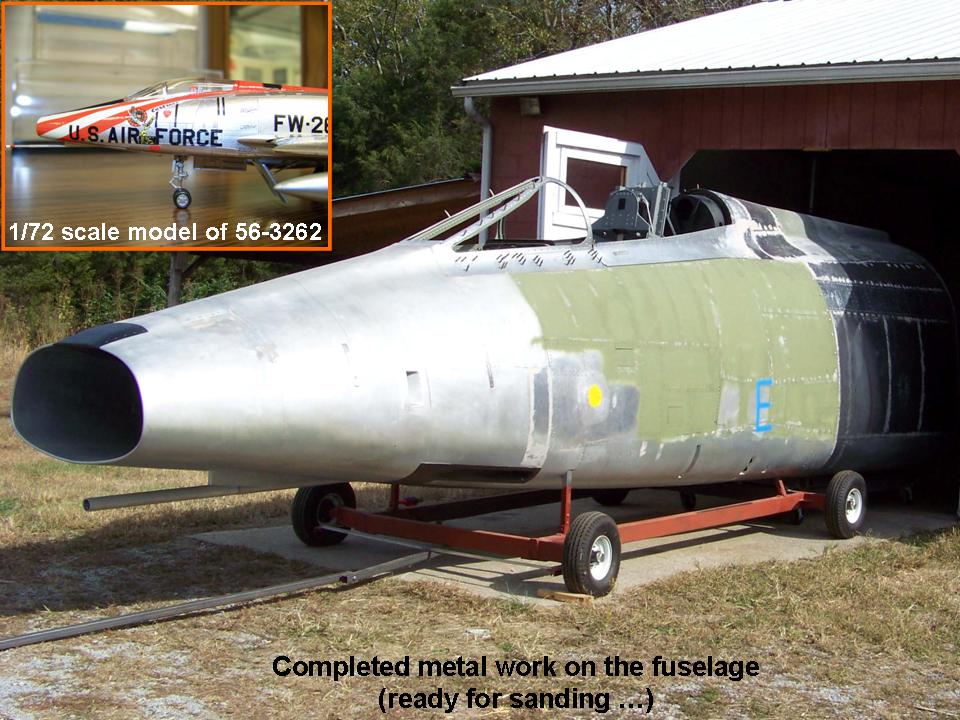 |
Canopy back deck 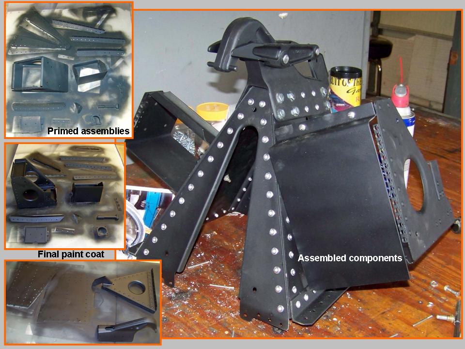 |
Installed components 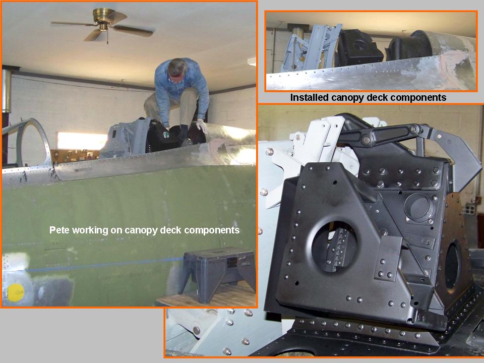 |
OK, most of the assembly work is done at this point. The next stage was prepping for the coming paint job. I've always been told that no paint job succeeds without a LOT of preparation, but there's no way I could have been prepared for the incredible amount of time it took to do all that Bondo work, followed by interminable hours of sanding.
The amount of Bondo we used was amazing. We used pop rivets to attach all the skin panels, so each pop rivet's center hole had to be filled in -- THOUSANDS of them. And then there were the inevitable little "dings" that occur during the construction process, not to mention all those spaces between the skin plates that had to be adjusted. Finally, we had done what we considered to be first-class metal work ... but in the harsh sunlight, the panels that had required considerable bending -- such as the spine panels -- showed that some of the curves were not uniform in the transition areas. Bondo works perfectly to correct such details.
Once the basic Bondo shaping and filling work was done, the excess Bondo was sanded off. The initial shaping was done with a rotary sander with 80-grit sandpaper, followed by "detail" shaping with 120-grit sandpaper. Prior to the application of the self-etching primer, the entire fuselage segment would have to be sanded with 320-grit paper. (If additional flaws showed up after the 320-grit sanding, those would require more Bondo and more sanding.) Next, the filler-primer coat would be applied, followed by 400-grit sanding.
Paint prepping is incredibly time-consuming. So, after just a few dozen hours of Bondo work and sanding, Steve and I realized that it would be REALLY nice if we could get some help. Fortunately, Steve knew Dave Graves, who was willing to put his considerable expertise to work on this project. (Aside from the fact that Dave really knew what he was doing, he also turned out to be a really nice guy. I guess that all of Steve's friends probably fit that description. Good people tend to attract good people ...)
The first cell in Figure 5 shows Dave and yours truly continuing the seemingly endless Bondo- and sanding work. The composite picture in cell 02 illustrates that the sanding goes on and on and on. (In between the sanding cycles, the need for more Bondo work became obvious, so back-and-forth we went.)
Figure 5, cell 03, shows the fuselage segment with its first filler-primer coat. At the time of this writing -- 26 November, 2010 -- the final paint prepping stage should require the investment of another 20-25 hours' worth of sanding, followed by another filler-primer coat and more sanding. When the sanding is finally done, we'll start painting ... but I suspect that it will be some time before that happens. (Painting is temperature-dependent and winter temperatures are not conducive to producing good painting results ...) In the meantime, we'll continue to work on the windscreen components and the canopy "glass" ... and the cockpit interior. I will document that work in Fuselage, Part 10.
Note: You can enlarge the pictures by clicking on them. Many of the pictures can be enlarged some more by placing the cursor on them and clicking again. Then maximize the window to get an even closer look.
|
Bondo patrol 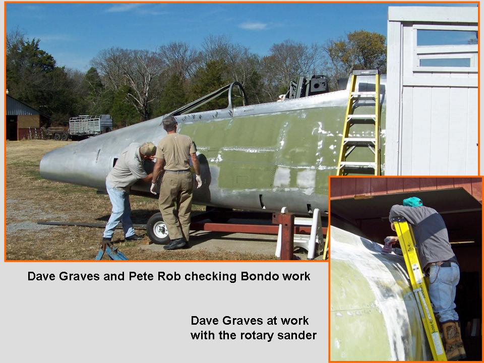 |
Lots of sanding 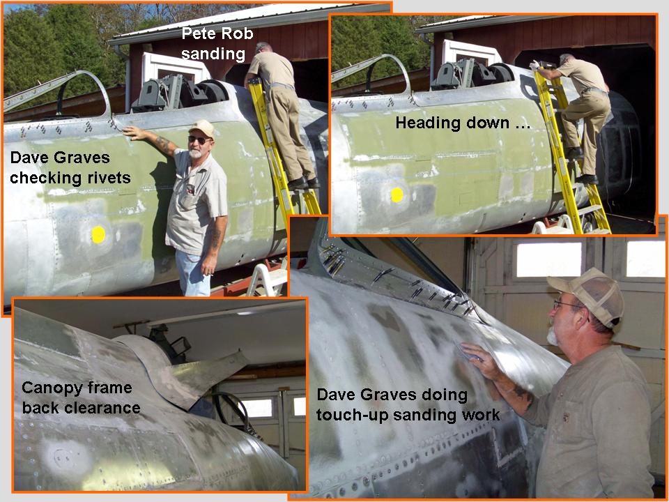 |
Filler-primer coat  |
And so the adventure continues ... Right now -- January 11, 2011 -- I'm hoping for some better temps so that we can roll "baby" outside for additional sanding -- and the subsequent painting. I'll start documenting that work in Fuselage, Part 10.
As this major "modeling" project moves forward, I will post pictures of the progress we're making. I may not be able to have a real F-100 ... but a properly constructed full-scale model will not be distinguishable from the real thing. Stay tuned.
While the rebuilding and restoring efforts are important, please remember that the main focus of the F-100 project is its database. If you can supply stories and pictures that reflect your experience with the Hun, please do so. (You can click on the Contact me link to send me an email.) The objective is to develop a very comprehensive personal history of the Hun and of the people who flew and maintained her. You and the Hun deserve to be remembered in your own words.
If you want to return to the home page, you can either click on the
Home link shown here or by clicking on the Home link shown on left side of your screen. (You can also use any of the navigation bar links shown on the bottom of the screen to move around this website.)