|
Pontiac M-39 Front 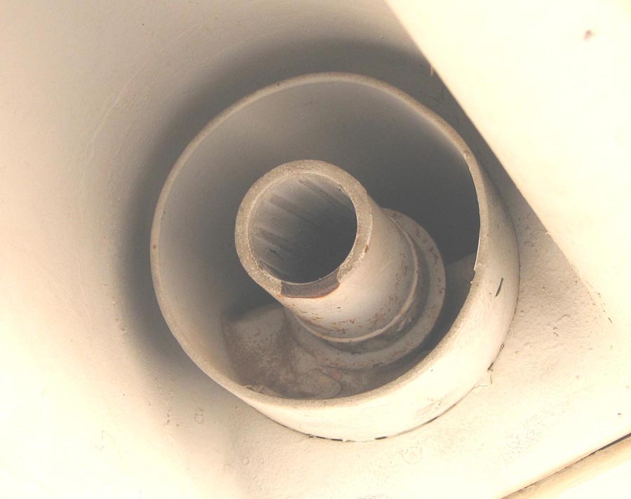 |
Raw material 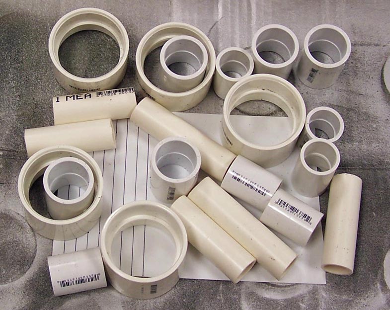 |
Initial Assembly. 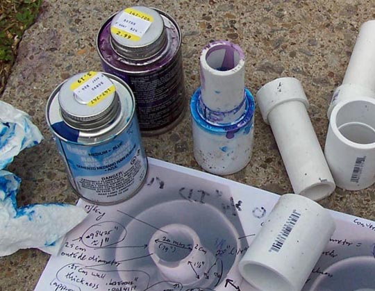 |
Much of the four Pontiac M-39 20 mm guns is hidden internally -- only the front few inches stick out of the back of the gun blast panels. Making those few inches turned out to be a challenge.
To make a realistic-looking gun, I needed a good set close-up photos. Unfortunately, none of the F-100 restorations I had seen at various museums had the guns installed, so my photo collection did not have a single M-39 picture in it. Even the beautifully restored F-100D at the AZ ANG base in Tucson lacked guns. (Thanks to Al "Smitty" Smith, I was able to take dozens of close-up photos of that aircraft. You can see some of those pictures by doing a database search for aircraft number 56-3055. You can check out Smitty's many story and photo contributions by searching the database.)
After weeks of unsuccessful web searching and many email requests, Pete Felts came to the rescue. When Pete made a trip to Tucson, he managed to get close to an F-100F at the AMARC base ... and he remembered my search for gun pictures. Bingo ... that aircraft did have the guns installed. (Pete Felts is a super source of all sorts of F-100 information. He knows that aircraft inside-out ... check out his story and photo contributions by searching the database.)
Figure 1, cell 1 shows the close-up that became the main source of
the gun model. The gun manual supplied the basic measurements to
augment the picture.
Cell 2 shows the basic "ingredients" for the gun model ...
bless PVC pipe, which comes in a wide variety of inside diameters
and wall thicknesses. The white plastic sheet is styrene plastic
that you can find in any well-stocked hobby store. Incidentally, the
wide PVC rings will become the Muzzle Gas Deflectors. (As usual,
Pete Felts provided the perfect explanation of what the MGDs do:
"Muzzle Gas Deflectors keep the gun gas from being forced into the
gun chamber when the gun is fired in flight. If the gas builds up in
the gun compartment, it can blow the door off and that ain't good."
Cell 3 shows the first rough assembly ... I used lots of PVC
starter (the purple stuff) and PVC glue (the blue stuff) to make
strong bonds and to help seal the edges. This part was completed
on 18 April, 2007.
Note: You can enlarge the pictures by clicking on them.
|
Pontiac M-39 Front |
Raw material |
Initial Assembly. |
After the initial assembly was completed, the barrel pieces were sanded.
Figure 2, cell 1 shows how it's done ... a good lawn chair works well,
especially after a 7-week layoff due to three surgeries on my left eye.
Not a bad way to spend some recovery time ... good weather, nice surroundings,
and lots of bird and insect songs. Tough job, eh?
Cell 2 shows the four guns. At this point, the pieces have not yet been
cut to the proper lenghts, but the black lines you see show that I have
already marked them for cutting.
Cell 3 shows the work that had to be done on the Muzzle Gas Deflectors.
Although the outside dimensions were perfect, the PVC connectors were too thick
to match the required 0.085-inch thickness ... and that meant shaving the
inside down. That work would have been really difficult if Steve Rettell
had not stepped in. (Steve's well-equipped shop, his wide-ranging expertise,
and his fine teaching skills are the basis for most of the F-100 "modeling"
work. You can see him at work by checking out the front end fuselage link.)
This picture shows the PVC piece in Steve's lathe.
|
Lots of sanding ... 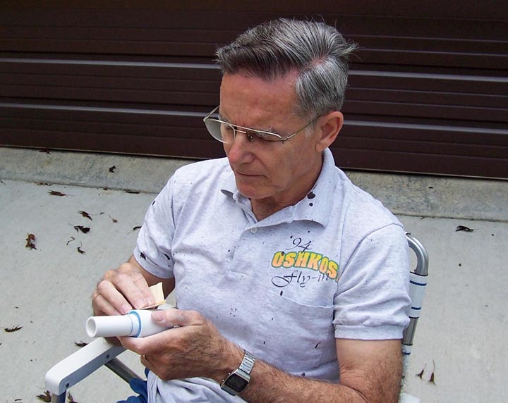 |
Ready for Cutting 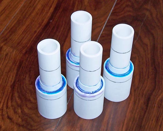 |
Lathe Work 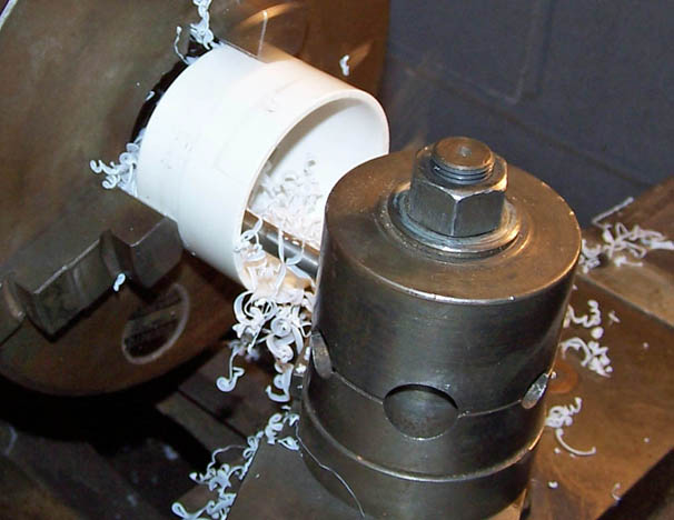 |
Figure 3, cell 1 shows me using Steve's lathe to do the precision cuts
that will produce the final length dimension. (Steve Rettell took the
picture while he made sure that his careful supervision kept me out of
trouble.)
Cell 2 shows the basic shape of completed guns. The lengths, inside
and outside diameters, and thicknesses are correct at this point.
Cell 3 shows the pieces after the bright silver paint was sprayed on.
The advantage of using such bright paint is that the smallest flaws show
up ... this picture shows that more smoothing and sanding is needed.
The final "gun metal" paint will be applied before the guns will be
installed.
Cell 4 shows the gun barrel assembly. Creating the rifling inside
the barrel was one of the jobs that required real patience. Steve created
a reaming tool to do the initial scoring for the rifling ... and then it
became a matter of simply spending hours with a small jewelry file to
get the rifling clean. Some paint helped create the "used" look. This
assembly still needs a little touch-up work, especially on the inside
of the Muzzle Gas Deflector. The rifling needs a little clean-up, too.
These finishing touches will be completed before the guns are installed
in the gun blast panels. (I just wanted to give to a preview!)
Cell 5 will show the installed guns. The (fiberglass) gun blast panels
are done at this point and they look like the real (titanium) deal.
Cell 6 is for those of you who might want to duplicate these guns
for your own project ... it would be great if this project would cause
more than a few people to build their own full-scale F-100 "models" ...
The picture shows a screen shot of the PowerPoint "gun construction
drawing" slide that I used to make the guns. The panel in the upper
right-hand corner shows the completed gun assembly.
|
Gun lathe work  |
Final dimensions 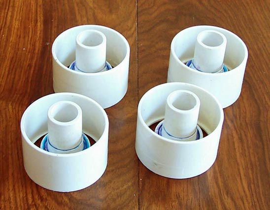 |
Bright silver paint 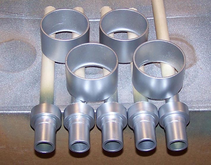 |
|
Barrel assembly 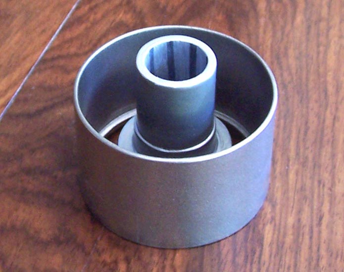 |
Installed guns  |
Gun dimensions  |
As this major "modeling" project moves forward, I will post pictures of the progress we're making. I may not be able to have a real F-100 ... but a properly contructed full-scale model will not be distinguishable from the real thing. Stay tuned.
Special note: Some years ago, I lost an opportunity to buy an F-100 cockpit procedures trainer. Although the cockpit in this trainer is not functional, it looks real enough ... and, most important, it includes the windscreen and the canopy. Having this piece of equipment will save at least a year of construction time. If you can help me find such a trainer, please contact me.
I need a set of F-100D fuselage blueprints to ensure that the formers and skin plates we cut are accurate. If you can give me some "heads-up" about where to buy such blueprints, I would sure like to hear from you!
If you want to return to the home page, you can either click
on the
Home
link shown here or by
clicking on the
Home
link shown on the navigation bar on the left side of your screen.
(You can always use any of the navigation bar links to move around
this website.)